Shading Context
The Shading context is among the most complex, displaying five Sub-contexts and several Panels. Many of these panels are condensed into a single Panel with Tabs in the default Blender settings.
Lamp Sub-Context
The settings in these Sub-contexts visualize the Lamp DataBlock. The Lamp Buttons are only displayed if the active Object is a Lamp.
Preview Panel
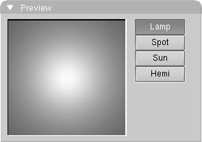
As for all these Sub-contexts, except radiosity, the first Panel contains a preview square window.
Right of the Window a column of four Toggle Buttons allows you to select the Lamp Type:
Spot
The lamp is restricted to a conical space. The 3DWindow shows the form of the spotlight with a broken line.
Lamp Panel
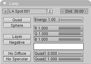
The top button row presents:
Users
If the Lamp Block is used by more than one Object, this button shows the total number of Objects. Press the button to make the Lamp "Single User". This duplicates the Lamp Block.
Dist
For the lamp types Lamp and Spot, the distance affects the intensity of the light. The standard formula is used for this:
D = "Dist" button, r = distance to the lamp. Light intensity = D/(D + r).
This is an inverse linear progression. With the option Quad, this can be changed.
Left button column presents:
Quad
The distance from the lamp is in inverse quadratic proportion to the intensity of the light. An inverse linear progression is standard (see the buttons Dist, Quad1 and Quad2).
Sphere
The lamp only sheds light within a spherical area around the lamp. The radius of the sphere is determined by the Dist button.
Layer
Only Objects in the same layer(s) as the Lamp Object are illuminated. This enables you to use selective lighting, to give objects an extra accent or to restrict the effects of the lamp to a particular space. It also allows you to keep rendering times under control.
No Specular
The lamp does not interact with the "Specular" shader of the object.
Right button column presents:
Energy
The intensity of the light. The standard settings in Blender assume that a minimum of two lamps are used.
Quad1, Quad2
The light intensity formula of a Quad Lamp is: Light intensity = D / (D + (quad1 * r) + (quad2 * r * r)) D = Dist button. r = distance to the lamp. The values of quad1 and quad2 at 1.0 produces the strongest quadratic progression. The values of quad1 and quad2 at 0.0 creates a special Quad lamp that is insensitive to distance.
Spot Panel
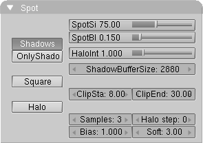
In the case of a Spot Lamp a full separate Panel is needed for additional settings. The left column contains:
Shadows
The lamp can produce shadows. Shadow calculations are only possible with the Spot lamps. The render option Shadows must also be turned ON in the DisplayButtons to enable Shadows at a global level.
OnlyShadow
For spot lamps (with Shadow ON), only the shadow is rendered. Light calculations are not performed and where there are shadows, the value of Energy is reduced.
Square
Spotlamps can have square Spotbundles with this option. For a better control over shadows and for slide projector effects.
Halo
The lamp has a halo. This only works with Spot lamps. The intensity of the halo is calculated using a conic section. With the option Halo step: it also uses the shadow buffer (volumetric rendering). The scope of the spot halo is determined by the value of Dist.
The right column contains:
SpotSi
The angle of the beam measured in degrees. Use for shadow lamp beams of less than 160 degrees.
Shadow Buffer
Blender uses a shadow buffer algorithm. From the spotlight, a picture is rendered for which the distance from the spotlight is saved for each pixel. The shadow buffers are compressed, a buffer of 1024x1024 pixels requires, on average, only 1.5 Mb of memory.
This method works quite quickly, but must be adjusted carefully. There are two possible side effects:
Aliasing. The shadow edge has a block-like progression. Make the spot beam smaller, enlarge the buffer or increase the number of Samples in the buffer.
Biasing. Faces that are in full light show banding with a block-like pattern. Set the Bias as high as possible and reduce the distance between ClipSta and ClipEnd.
ClipSta, ClipEnd
Seen from the spot lamp: everything closer than ClipSta always has light; everything farther away than ClipEnd always has shadow. Within these limits, shadows are calculated. The smaller the shadow area, the clearer the distinction the lamp buffer can make between small distances, and the fewer side effects you will have. It is particularly important to set the value of ClipSta as high as possible.
Samples
The shadow buffer is 'sampled'; within a square area a test is made for shadow 3*3, 4*4 or 5*5 times. This reduces the aliasing.
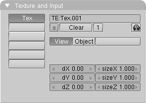
Texture and Input Panel
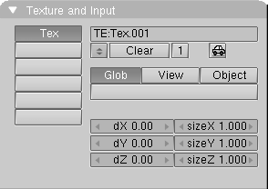
This texture panel, and the following are a simplified version of the Material texture panels.
Left column contains:
Texture Channels
A Lamp has six channels with which Textures can be linked. Each channel has its own mapping, i.e. the manner in which the texture works on the lamp. The settings are in the buttons described below and in the Map To Panel.
Right column contains:
Texture Data Block
Texture Mapping Input
Each Texture has a 3D coordinate (the texture coordinate) as input. The starting point is always the global coordinate of the 3D point that is seen in the pixel to be rendered. A lamp has three options for this.
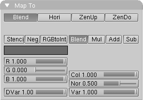
Map To Panel
Stencil
Normally, textures are executed one after the other and placed over each other. A second Texture channel can completely replace the first. This option sets the mapping to stencil mode. No subsequent Texture can have an effect on the area the current Texture affects.
Material Sub-Context
The settings in this ButtonsWindow visualize the Material DataBlock. The Material Panels and Buttons are only displayed if the active Object has a Material.
Preview Panel
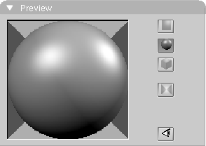
As for all these Sub-contexts, except radiosity, the first Panel contains a preview square window.
The top three buttons on the left governs the preview:
Sphere
In the sphere-preview the Z axis is the vertical axis for the preview sphere; the X and Y axes revolve around this axis.
Material Panel
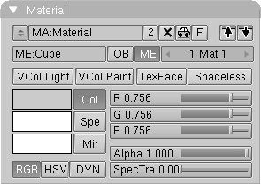
The very top row is related to the Material Data Block.
Users
If the Material block is used by more than one Object, this button indicates the total number of users. Press the button to make the Material "Single User". An exact copy is created.
Fake User
Blender assigns a "Fake" user to the material, so that it is saved in the .blend file even if unlinked.
Copy to buffer
The complete settings for the Material and all the mapping are copied to a temporary buffer.
Copy from buffer
The temporary buffer is copied to the Material.
These row or buttons immediately below specify what the Material block is linked to, or must be linked to. By linking Materials directly to Objects, each Object is rendered in its own Material.
ME:
This Button indicates the block to which the Material is linked. This button can only be used to give the block another name. Possible blocks are:
ME: Material is linked to a Mesh (ObData) block.
CU: Material is linked to a Curve, Surface or Font (ObData) block.
MB: Material is linked to a MetaBall (ObData) block.
OB: Material is linked to the Object itself.
OB
Use this button to link the current Material to the Object. Any link to the ObData block remains in effect. Links can be removed with the remove link button in top row.
1 Mat 1
An Object or ObData block may have more than one Material. This button can be used to specify which of the Materials must be displayed, i.e. which Material is active. The first digit indicates how many Materials there are; the second digit indicates the number of the active Material. Each face in a Mesh has a corresponding number: the 'Material index'. The number of indices can be specified with the EditButtons. Curves and Surfaces also have Material indices.
Third row of buttons governs:
VCol Light
If the Mesh vertex has colours (see Vertex Paint), they are added to the Material as extra light. The colours also remain visible without lamps. Use this option to render radiosity-like models.
VCol Paint
If the Mesh vertex has colours, this button replaces the basic colour of the Material with these colours. Now light must shine on the Material before you can see it.
Shadeless
This button makes the Material insensitive to light or shadow.
The block below defines at a time the Three colors of the material and the behavior of the Object in Real Time simulations. This is selected with the bottom row of Toggle Buttons:
RGB
Most colour sliders in Blender have two pre-set options: in this case, the colour is created by mixing Red, Green, Blue.
HSV
The colour sliders mix colour with the Hue, Saturation, Value system. 'Hue' determines the colour, 'Saturation' determines the amount of colour in relation to grey and 'Value' determines the light intensity of the colour.
DYN
Adjust parameters for the dynamics options. The neighbouring buttons changes completely.
For the Colours, whichever the mapping, above these Toggle Buttons there are three more Toggle Buttons on a column, with colour preview on their left:
Mir
The mirror colour of the Material. This affects a environment or reflection map.
The color, selected by its Toggle Button, can be edited with the three Num Buttons on the right which, depending on color scheme, are:
Alpha
The degree of coverage, which can be used to make Materials transparent. Use the option ZTransp to specify that multiple transparent layers can exist. Without this option, only the Material itself is rendered, no matter what faces lie behind it. The transparent information is saved in an alpha layer, which can be saved as part of a picture.
Shaders Panel

This Panel presents the Diffuse and Specular shader settings on the left and a column of Toggle Buttons on the right. On the left:
Diffuse Shader Menu
Three Diffuse Shaders are coded in Blender, depending on which is chosen the Num Buttons immediately on the right changes:
Lambert - Blender default diffuse shader since ever. Parameters:
Ref Strength of reflectivity
Oren-Nayar - Blender new physical shader (v. 2.28). Parameters:
Ref Strength of reflectivity
Rough Roughness of the surface
Toon - Blender new cartoon shader (v2.28). Parameters:
Ref Strength of reflectivity
Size Angular width of lit region
Smooth Blurriness of light/shadow boundary
Specular Shader Menu
Four Specular Shaders are coded in Blender, depending on which is chosen the Num Buttons immediately on the right changes:
CookTorr - Blender default specular shader since ever. Parameters:
Spec Strength of Specularity
Hard The hardness of the specularity. A large value gives a hard, concentrated sheen, like that of a billiard ball. A low value gives a metallic sheen.
Phong - Blender Phong shader (v. 2.28). Parameters:
Spec Strength of Specularity
Hard The hardness of the specularity. A large value gives a hard, concentrated sheen, like that of a billiard ball. A low value gives a metallic sheen.
Blinn - Blender Physical shader (v2.28). Parameters:
Spec Strength of Specularity
Hard The hardness of the specularity. A large value gives a hard, concentrated sheen, like that of a billiard ball. A low value gives a metallic sheen.
Refr Refractive index to compute specularity. This does not include mirror-like reflections or glass-like refractions.
Toon - Blender new cartoon shader (v. 2.28). Parameters:
Spec Strength of Specularity
Size Angular width of specular region
Smooth Blurriness of specular/diffuse boundary
The bottom four Num Buttons are:
Amb
The degree to which the global Ambient colour is applied, a simple form of environmental light. The global Ambient can be specified in the World Sub-context. Ambient is useful for giving the total rendering a softer, more coloured atmosphere.
Add
This option adds some kind of glow to transparent objects, but only works with the unified renderer.
Zoffset
This button allows you to give the face to be rendered an artificial forward offset in Blender's Zbuffer system. This only applies to Materials with the option ZTransp. This option is used to place cartoon figures on a 3D floor as images with alpha. To prevent the figures from 'floating', the feet and the shadows drawn must be placed partially beneath the floor. The Zoffset option then ensures that the entire figure is displayed. This system offers numerous other applications for giving (flat) images of spatial objects the appropriate 3D placement.
The rightmost column of Toggle Buttons contains:
Halo
This buttons turns a regular material into a Halo material. both the Material and this Panel dramatically change. They are described below.
Traceable
This specifies whether or not shadow lamps can 'see' the current Material. That is if object cast shadows.
Shadow
This button determines whether the Material can receive a shadow, that is if object receive castshadows.
Wire
Only the edges of faces are rendered (normal rendering!). This results in an exterior that resembles a wire frame. This option can only be used for Meshes.
ZTransp
Transitional Zbuffers can only render opaque faces. Blender uses a modified method to Zbuffer transparent faces. This method requires more memory and calculation time than the normal Zbuffer, which is why the two systems are used alongside each other.
Env
Environment option. The Material is not rendered and the Zbuffer and render buffers are 'erased' so that the pixel is delivered with Alpha = 0.0.
Preview Panel for Halo Materials
If a Material has the option Halo ON, a number of buttons change to specific halo settings. Lens flares can also be created here. Halos are rendered on the 3D location of the vertices. These are small, transparent round spots or pictures over which circles and lines can be drawn. They take Blender's Zbuffer into account; like any 3D element, they can simply disappear behind a face in the forefront.
Halos are placed over the currently rendered background as a separate layer, or they give information to the alpha layer, allowing halos to be processed as a post-process.
Only Meshes and Particle Effects can have halos. A Mesh with a halo is displayed differently in the 3DWindow; with small dots at the position of the vertices. Halos cannot be combined with 'ordinary' faces within one Mesh.
As for all these Sub-contexts, except radiosity, the first Panel contains a preview square window.
The preview now show the halo material, the top three buttons on the left loose functionality, the bottom two keep the functionalities they had for normal materials.
Material Panel for Halo Materials
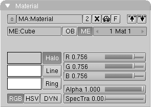
The two top rows related to the Material Data Block maintains the meaning they had for normal Materials. The third line disappears and the bottom part of the Panel maintains the general functionality but colors now refer to:
Ring
The base color of the Halo Ring, if any.
The color, selected by its Toggle Button, can be edited with the three Num Buttons on the right which, depending on color scheme, are:
Alpha
The degree of coverage, which can be used to make Materials transparent. Use the option ZTransp to specify that multiple transparent layers can exist. Without this option, only the Material itself is rendered, no matter what faces lie behind it. The transparent information is saved in an alpha layer, which can be saved as part of a picture.
Shaders Panel for Halo Materials
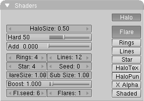
This Panel presents the Halo shader settings on the left and a column of Toggle Buttons on the right. On the left:
Add
Normally, the colour of halos is calculated during rendering, giving a light emitting effect. Set the "Add" value to 0.0 to switch this off and make black or 'solid' halos possible as well.
Rings
The number of rings rendered over the basic halo, if the corresponding toggle button on the right is enabled.
Lines
The number of sparkle-shaped lines rendered over the basic halo, if the corresponding toggle button on the right is enabled.
Star
The number of points on the star-shaped basic halo, if the corresponding toggle button on the right is enabled.
Seed
'Random' values are selected for the dimension of the rings and the location of the lines based on a fixed table. Seed determines an offset in the table.
If the Halo is of Flare type, selected with toggle Button on the right, five further Num Buttons appear:
Fl.seed
The dimension and shape of the sub Flares is determined by a fixed table with 'random' values. Fl.seed specifies an offset in the table.
Flare
Each halo is now also rendered as a lens flare. This effect suggests the reflections that occur in a camera lens if a strong light source shines on it. A Flare consists of three layers:
the ordinary halo, which has a 3D location, and can thus disappear behind a face.
the basic Flare, which is the same halo, but possibly with other dimensions. This is placed over the entire rendering as a post-process.
the sub Flares, multi-coloured dots and circles, that are also placed over the entire rendering as a post-process.
The HaloSize value not only determines the dimensions, but is also used to determine the visibility - and thus the strength - of the Flare rendered in the post-process. This way, a Flare that disappears slowly behind a face will decrease in size at a corresponding speed and gradually go out.
Star
Instead of being rendered as a circle, the basic halo is rendered in the shape of a star. The NumBut Star determines the number of points the star has.
HaloTex
Halos can be given textures in two ways:
HaloTex OFF: the basic colour of each halo is determined by the texture coordinate of the halo-vertex.
HaloTex ON: each halo gets a complete texture area, in which, for example, an Image texture is displayed completely in each basic halo rendered.
HaloPuno
The vertex normal ("Puno" in Blender's turbo language) is used to help specify the dimension of the halo. Normals that point directly at the Camera are the largest; halos with a normal that point to the rear are not rendered. If there are no vertex normals in the Mesh (the Mesh only consists of vertices) the normalized local coordinate of the vertex is used as the normal.
Texture Panel
Material textures are the most complex in Blender. There are three panels devoted to them. This first is concerned with texture channels, the second governs the Input mapping, the last the output mapping.
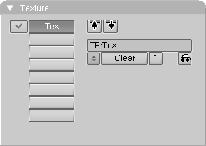
Texture channels
A Material has eight channels to which Textures can be linked. Each channel has its own mapping, which is the effect the texture has on the material.
Channels are grouped on a column on the left. For each active channel a Toggle button appears, allowing to switch off each single texture channel.
Copy to buffer
The up pointing arrow on the right of the Panel copies the complete mapping settings to a temporary buffer.
Copy from buffer
The down pointing arrow on the right of the Panel pastes the complete mapping settings from the temporary buffer.
Map Input Panel
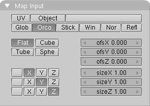
Each Texture has a 3D coordinate (the texture coordinate) as input. The starting point is generally the global coordinate of the 3D point that can be seen in the pixel to be rendered. A Material has the following Mapping options, given by the first two row of buttons:
UV
The U-V coordinates of a face or Nurbs surface from an Object make up the texture coordinates. U-V is a commonly used term for specifying the mathematical space of a flat or curved surface.
Object
Every Object in Blender can be used as a source for texture coordinates. For this, the Object's inverse transformation is applied to the global coordinate, which gives the local Object coordinate. This links the texture to the position, dimension and rotation of the Object. Generally, an Empty Object is used to specify the exact location of a Texture, e.g. to place a logo on the body of an airplane. Another commonly used approach is to have the 'Texture Object' move to achieve an animated texture.
Object Name
The name of the Object used for the texture coordinates must be placed in this Text Button. If the Object does not exist, the button remains empty.
Stick
Sticky texture. Blender allows you to assign a texture coordinate to Meshes, which is derived from the manner in which the Camera view sees the Mesh. The screen coordinate (only X,Y) for each vertex is calculated and saved in the Mesh. This makes it appear as if the texture is projected from the Camera; the texture becomes "sticky" (see also Make Sticky in the EditButtons). Use Sticky to precisely match a 3D object with an Image Texture. Special morphing effects can also be achieved.
Win
The screen coordinate (X,Y) is used as a texture coordinate. Use this method to achieve 2D layering of different Images.
Nor
The normal vector of the rendered face is used as a texture coordinate. Use this method to achieve reflection mapping, which is the suggestion of mirroring using a specially pre-calculated Image.
Refl
The reflection vector of the rendered face is used as a texture coordinate. This vector points in a direction that makes the face appear to be mirrored. Use this option to suggest a reflected surface with procedural textures such as "Marble" or "Clouds" and of course for the use with the EnvMap texture.
Mapping: 3D to 2D
For Image Textures only; the four buttons middle left in the Panel determines the manner is which the 3D coordinate is converted to 2D.
Cube
Depending on the normal vector of the face, the X-Y or the X-Z or the Y-Z coordinates are selected. This option works well for stones, marbles and other regular textures,
Map To Panel
The Map To Panel determines the effect of the Texture output for the current point.
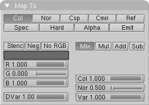
Mapping: output to.
The top two rows of Buttons determines which property of the material is affected:
Nor
The texture affects the rendered normal direction. It is a three state button, effects can be off, positive or negative. Only important for Image textures. The Stucci is the only procedural texture which effectively generate normal informations (for now).
Ref
The texture affects the value of the material's reflectivity . This if a three state button: off, active and inverse.
Spec
The texture affects the value of specularity of the material. This if a three state button: off, active and inverse.
Mapping: Texture additional settings.
The group of buttons bottom left on the panel defines further settings on how the Texture output is handled.
Stencil
Normally, textures are executed one after the other and laid over one another. A second Texture channel can completely replace the first. With this option, the mapping goes into stencil mode. No subsequent Texture can have an effect on the area the current Texture affects.
Texture Sub-Context
If there is an active Texture channel in a Material, Lamp or World Block, switching to Texture Sub-Context (F6) populates the Buttons Window wit Texture panels of the current Texture Block.
Each Texture has a 3D coordinate (the texture coordinate) as input, as described in the Material Sub-context. What happens in the Texture evaluation process is determined by the type of texture:
Intensity textures: return one scalar value. The preview render in this window shows this as grey values.
RGB textures: returns three, RGB, values; they always work on colour.
Bump textures: returns three values; they always work on the normal vector. Only the "Stucci" and "Image" texture can give normals.
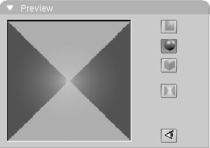
Preview Panel
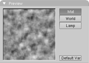
As for all these Sub-contexts, except radiosity, the first Panel contains a square preview window.
Right of the Window a column of three Toggle Buttons allows you to select the Block of Textures, Blender automatically selects the right one:
Texture Panel
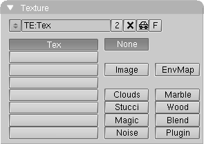
The Texture Block in the top row indicate what Texture block is visualized.
Users
If the Texture block has more than one user, this button shows the total. Press the button to make the Texture "Single User". An exact copy is then created.
Fake User
Blender assigns a "Fake" user to the texture, so that it is saved in the .blend file even if unlinked.
Below the Texture Block there are three columns of buttons, on the left:
Texture Channels
Eight or six buttons, depending if we are working on a Material, on a Lamp or on the World, showing the active Texture channels with their names.
The two columns on the right select the type of texture. There are 11 types one of which, none effectively is "no texture". Each of the other buttons select a particular kind of texture and opens at least a new, type-dependent, Panel. Texture types will be described in the relevant Panel description
Colors Panel
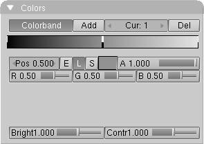
This panel allows you to create a smooth colour progression in place of an Intensity progression. Intensity textures are thus changed into an RGB texture. The use of Colorband with a sharp transition can cause aliasing.
Pos:
The position of the active colour. Values range from 0.0 to 1.0. This can also be entered using LeftMouse (hold-move) in the Colorband.
E, L, S
The interpolation type with which colours are mixed, i.e. 'Ease', 'Linear' and 'Spline'. The last gives the most fluid progression.
Image Texture Panel
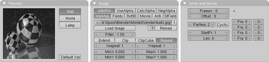
Of the ten possible texture the Image one is the only requiring twoadditional Panels, this, and the Cropand Anim one.
The Image texture is the most frequently used and most advanced of Blender's textures. The standard bump-mapping and perspective-corrected MipMapping, filtering and anti-aliasing built into the program guarantee outstanding image quality. Because pictures are two-dimensional, you must specify in the mapping buttons how the 3D texture coordinate is converted to 2D; mapping is a part of the MaterialButtons. For best results UV mapping is required.
The first two row of Buttons in the Panel determines:
InterPol
This option interpolates the pixels of an Image. This becomes visible when you enlarge the picture. Turn this option OFF to keep the pixels visible - they are correctly anti-aliased. This last feature is useful for regular patterns, such as lines and tiles; they remain 'sharp' even when enlarged considerably.
MipMap
Generates a series of pictures, each half the size of the former one. This optimizes the filtering process. When this option is OFF, you generally get a sharper image, but this can significantly increase calculation time if the filter dimension becomes large.
Fields
Video frames consist of two different images (fields) that are merged by horizontal line. This option makes it possible to work with field images. It ensures that when "Fields" are rendered the correct field of the Image is used in the correct field of the rendering. MipMapping cannot be combined with "Fields".
Movie
Movie files (AVIs supported by Blender, SGI-movies) and "anim5" files can also be used for an Image. In this case the subsequent Panel, Crop and Anim is populated by Buttons.
Anti
Graphic images such as cartoons and pictures that consist of only a few colors with a large surface filling can be anti-aliased as a built in pre-process.
St Field
Normally, the first field in a video frame begins on the first line. Some frame grabbers do this differently!
The following two lines presents the image Menu:
Image menu
You can select a previously created Image from the list provided. Image blocks can be reused without taking up extra memory.
Users
Indicates the number of users for the Image. The "Single User" option cannot be activated here. It has no significance for Images.
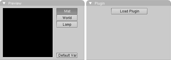
Load Image
The (largest) adjacent window becomes an Image Select Window. Specify here what file must be read to become an Image.
The small, labelless, button on the right does the same thing, but now simply gives a File Select Window.
Pack
Indicates the packing of the image. Pressed means the image is packed into the Blend-file. Clicking on the Button packs or unpacks the image. If a unpack option is triggered the unpack-menu pops up.
Filter
The filter size used by the options MipMap and Interpol.
The following options determine what happens if the texture coordinate falls outside the Image.
Clip
Outside the Image, an alpha value of 0.0 is returned. This allows you to 'paste' a small logo on a large object.
ClipCube
The same as Clip, but now the 'Z' coordinate is calculated as well. Outside a cube-shaped area around the Image, an alpha value of 0.0 is returned.
Crop and Anim Panel
This Panel is strictly related to the Image and is present only for Image type textures.
Frames
This activates the animation option; another image file (in the same Image block) will be read per rendered frame. Blender tries to find the other files by changing a number in the file name. Only the rightmost digit is interpreted for this. For example: 01.ima.099.tga + 1 becomes 01.ima.100.tga. The value of "Frames" indicates the total number of files to be used. If the option "Movie" is ON, this value must also be set. Now, however, a frame is continually taken from the same file.
Fie/Ima
The number of fields per rendered frame. If no fields are rendered, even numbers must be entered here. (2 fields = 1 frame).
Clouds Texture Panel
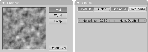
The "Clouds" is a procedural texture. This means that each 3D coordinate can be translated directly to a colour or a value. In this case, a three-dimensional table with pseudo random values is used, from which a fluent interpolation value can be calculated with each 3D coordinate (thanks to Ken Perlin for his masterful article "An Image Synthesizer", from the SIGGRAPH proceedings 1985). This calculation method is also called Perlin Noise.
Stucci Texture Panel
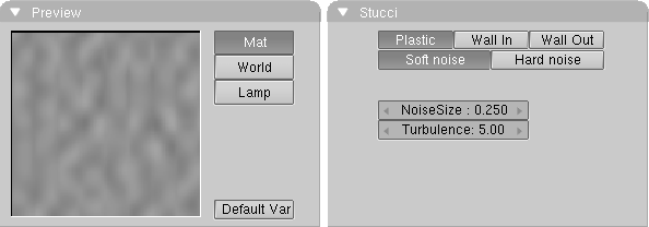
This procedural texture generates Noise-based normals.
Magic Texture Panel
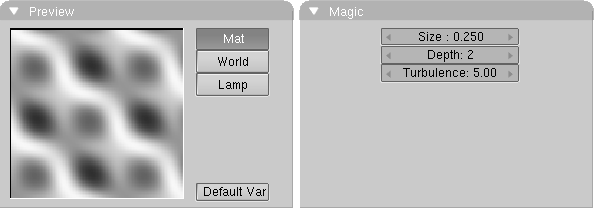
Magic is a procedural texture. The RGB components are generated independently with a sine formula.
Noise
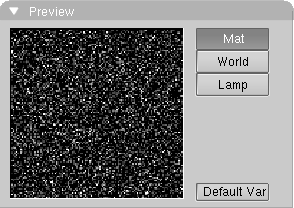
Although this looks great, it is not Perlin Noise! This is a true, randomly generated Noise. This gives a different result every time, for every frame, for every pixel.
It has no parameters and hence no Panel of its own.
EnvMap Texture Panel
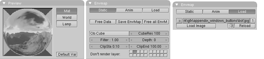
Blender uses cube-mapped environmental maps to fake reflections. This is a very peculiar texture computed at rendering time from the point of view of a given Object. Blender allows three types of environment maps:
Dynamic
The map is calculated each time a rendering takes place. This means moving Objects are displayed correctly in mirroring surfaces.
Load
When saved as an image file, environment maps can be loaded from disk. This option allows the fastest rendering with environment maps.
Free Data
This action releases all images associated with the environment map. This is how you force a recalculation when using a Static map.
Save EnvMap
You can save an environment map as an image file, in the format indicated in the Scene Context (F10).
Free all Env
This button does notonly releases all images linked to the current EnvMap but also all other images linked to any other EnvMap in the whole scene.
If the environment map type is "Load". The environment map image can be loaded via a regular Image block in the Blender structure:
Load Image
The (largest) adjacent window becomes an Image Select Window. Specify here what file to read in as environment map. If the loaded image is not a Blender EnvMap weirs results can occur at rendering time.
Image Menu
You can select a previously loaded map from the list provided. EnvMap Images can be reused without taking up extra memory.
Ob:
Fill in the name of an Object that defines the center and rotation of the environment map. This can be any Object in the current Scene.
Depth:
Forces the EnvMap to be computed this number of additional times. This is usefull is several Objects are mirroring each one the other and multiple reflections occur.
Marble Texture Panel
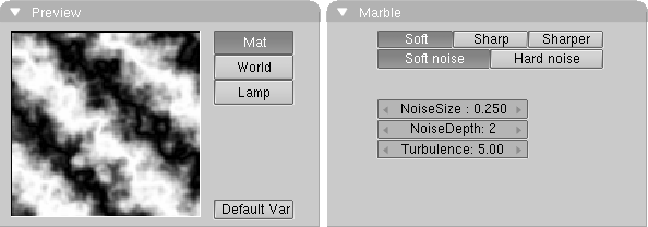
"Marble" is another procedural texture. In this case, bands are generated based on a sine formula and Noise turbulence. It returns an Intensity value only.
Wood Texture Panel
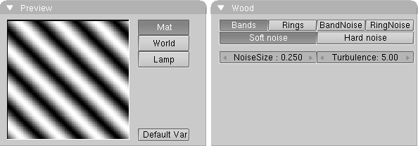
"Wood" is another procedural texture. In this case, bands are generated based on a sine formula. You can also add a degree of turbulence with the Noise formula. It returns an Intensity value only.
Radiosity Sub-Context
Radiosity has been a modelling tool up to Blender 2.28, and is now both a modelling and a rendering tool. The Radiosity Sub-context reflects this duality.
By default it presents two Panels: Radio Render to set the parameters of Radiosity Renderingand Radio Tool to set the parameters for the modelling radio tool. In this latter case a new Panel, Calculation appears.
Radio Render Panel
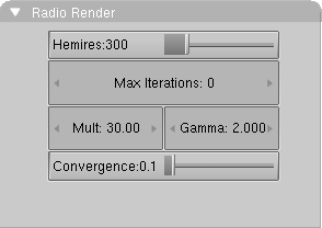
This is presents parameters for Radiosity as a rendering tool, but its entries are also usefull in Radiosity modelling. Radiosity Rendering takes into account only Objects whose Materials have the Radio Toggle Button enabled.
Hemires
The size of a hemicube; the color-coded images used to find the Elements that are visible from a 'shoot Patch', and thus receive energy. Hemicubes are not stored, but are recalculated each time for every Patch that shoots energy. The Hemires value determines the Radiosity quality and adds significantly to the solving time.
Max iterations
When this button has a non-zero value, Radiosity solving stops after the indicated iteration step, unless the convergence criterion is met beforehand.
Mult, Gamma
The colorspace of the Radiosity solution is far more detailed than can be expressed with simple 24 bit RGB values. When Elements are converted to faces, their energy values are converted to an RGB color using the Mult and Gamma values. With the Mult value you can multiply the energy value, with Gamma you can change the contrast of the energy values.
Convergence
When the amount of unshot energy in an environment is lower than this value, the Radiosity solving stops. The initial unshot energy in an environment is multiplied by the area of the Patches. During each iteration, some of the energy is absorbed, or disappears when the environment is not a closed volume. In Blender's standard coordinate system a typical emitter (as in the example files) has a relative small area. The convergence value in is divided by a factor of 1000 before testing for that reason .
Radio Tool Panel
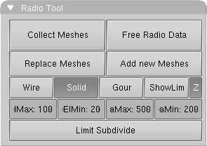
Collect Meshes
All selected and visible Meshes in the current Scene are converted to Patches. As a result some Buttons in the interface change color and a new Panel, Calculation, appears. Blender now has entered the Radiosity mode, and other editing functions are blocked until the button Free Data is pressed. After the Meshes are collected, they are drawn in a pseudo lighting mode that clearly differs from the normal drawing.
Free Radio Data
All Patches, Elements and Faces are freed in Memory. You always must perform this action after using Radiosity to be able to return to normal editing.
Replace Meshes
Once the Radiosity process has been performed, by clicking this button the faces of the current displayed Radiosity solution are converted to Mesh Objects with vertex colors. A new Material is added that allows immediate rendering. The input-Meshes are lost.
Wire, Solid, Gour
Three drawmode options are included which draw independent of the indicated drawmode of a 3DWindow. Gouraud display, the smoothest, is only performed after the Radiosity process has started.
ShowLim, Z
This option visualizes the Patch and Element limits. By pressing the 'Z' option, the limits are drawn rotated differently. The white lines show the Patch limits, cyan lines show the Element limits.
Calculation Panel
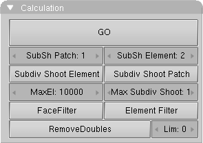
This Panel actually launches a RadiosityModelling solution and handles its post-processing.
GO
With this button you start the Radiosity simulation. The phases are:
Limit Subdivide. When Patches are too large, they are subdivided.
Subdiv Shoot Patch. The value of SubSh P defines the number of times the "Subdiv Shoot Patch" function is called. As a result, Patches are subdivided.
Subdiv Shoot Elem. The value of SubSh E defines the number of times the "Subdiv Shoot Element" function is called. As a result, Elements are subdivided.
Subdivide Elements. When Elements are still larger than the minimum size, they are subdivided. Now, the maximum amount of memory is usually allocated.
Solve. This is the actual 'progressive refinement' method. The mousecursor displays the iteration step, the current total of Patches that shot their energy in the environment. This process continues until the unshot energy in the environment is lower than the Convergence or when the maximum number of iterations has been reached.
Convert to faces. The elements are converted to triangles or squares with 'anchored' edges, to make sure a pleasant not-discontinue Gouraud display is possible.
SubSh Element
The number of times the environment is tested to detect Elements that need subdivision.
Subdiv Shoot Patch
By shooting energy to the environment, errors can be detected that indicate a need for further subdivision of Patches. The subdivision is performed only once each time you call this function. The results are smaller Patches and a longer solving time, but a higher realism of the solution. This option can also be automatically performed when the GO action has started (see above).
Subdiv Shoot Element
By shooting energy to the environment, and detecting high energy changes (frequencies) inside a Patch, the Elements of this Patch are selected to be subdivided one extra level. The subdivision is performed only once each time you call this function. The results are smaller Elements and a longer solving time and probably more aliasing, but a higher level of detail. This option can also be automatically performed when the GO action has started (see above).
MaxEl
The maximum allowed number of Elements. Since Elements are subdivided automatically in Blender, the amount of used memory and the duration of the solving time can be controlled with this button. As a rule of thumb 20,000 elements take up 10 Mb memory.
Max Subdiv Shoot
The maximum number of shoot Patches that are evaluated for the "adaptive subdivision". If zero, all Patches with a non zero Emit value are evaluated.
FaceFilter
After Radiosity calculation has occurred, Elements are converted to faces for display. A "FaceFilter" forces an extra smoothing in the displayed result, without changing the Element values themselves.
Element Filter
After Radiosity calculation has occurred, this option filters Elements to remove aliasing artifacts, to smooth shadow boundaries, or to force equalized colors for the RemoveDoubles option.
World Sub-Context
The settings in this ButtonsWindow visualize the World DataBlock. It is linked to a Scene, and can therefore be reused by other Scenes. This block contains the settings for standard backgrounds, mist effects and the built-in star generator. The ambient colour and exposure time can be set here as well.
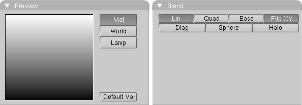
Preview Panel
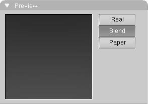
As for all these Sub-contexts, except radiosity, the first Panel contains a preview square window.
Right of the Window a column of three Toggle Buttons allows you to select the background type:
Blend
This option renders the background, the sky, with a natural progression. At the bottom of the image is the horizon colour, at the top, the colour of the zenith. The progression is not linear, but bent in the shape of a ball, depending on the lens value of the Camera.
World Panel
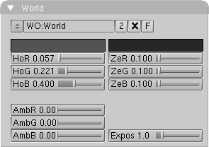
World DataBlock
The top row in this panel contains the World Data Block:
ZeR, ZeG, ZeB
The colour of the zenith. This is the point directly above or directly below an observer (on the earth!).
Mist, Star, Physics Panel
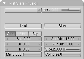
The first row of this Panel is dedicated to the Realtime Physics engine:
Mist
Activates the rendering of mist. All rendered faces and halos are given an extra alpha value, based on their distance from the camera. If a 'sky' colour is specified, this is filled in behind the alpha.
Qua, Lin, Sqr
Determines the progression of the mist. Quadratic, linear or inverse quadratic (square root), respectively. Sqr gives a thick 'soupy' mist, as if the picture is rendered under water.
Hi
With this option, the mist becomes thinner the higher it goes. This is measured from Z = 0.0. If the value of Hi is set to zero, this effect is turned off.
Stars
Blender has an automatic star generator. These are standard halos that are only generated in the sky. With this option ON, stars are also drawn in the 3DWindow (as small points).
StarDist
The average distance between two stars. Do not allow this value to become too small, as this will generate an overflow.
Texture and Input Panel
This texture panel, and the following are a simplified version of the Material texture panels.
Left column contains:
Texture Channels
A World has six channels with which Textures can be linked. Each channel has its own mapping, i.e. the manner in which the texture works on the world. The settings are in the buttons described below and in the Map To Panel.
Right column contains:
Texture Data Block
Texture Mapping Input
Each Texture has a 3D coordinate (the texture coordinate) as input. The starting point is always the global coordinate of the 3D point that is seen in the pixel to be rendered. A world has only two options for this.
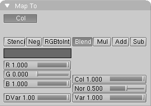
Map To Panel
The texture can only affect the colour of the background. This can occur according to 4 schemes:
Stencil
Normally, textures are executed one after the other and placed over each other. A second Texture channel can completely replace the first. This option sets the mapping to stencil mode. No subsequent Texture can have an effect on the area the current Texture affects.