This document describes the structure of Blender, and the reasoning
behind this structure. It provides a high-level view of the components
that make up Blender, and their interactions. When Blender needs to
change, it should be consistent with this overall view.
This document describes the structure of Blender. It gives a
break-down of the functionality, and a description of all interfaces
that are used between parts.
2. Top level requirements
Top-level requirements (to be filled in).
3. Functional decomposition
This section details the relations between different kinds of
functionality wrapped in modules, and the specific functionality that
is currently contained in them. This is a description of how we want
the system to be in the end, and not the current situation. A
description of the current implementation is given in Section 3.
The internal structure of modules is a separate issue. A description
of this structure is given elsewhere.
3.1. Top-level system view
There are several kinds of modules in the Blender system. Each type of
module has distinct responsibilities attaches to it.
mainloop: This type of module contains services that are
tied together to deliver the functional part of Blender. Here you
would typically find a game-engine framework, an editor
framework. Frameworks will in general use a lot of knowledge about the
modules they use. However, they should abstract in the actual calling
of these modules as much as possible.
handleable: This type of module provides services of a
certain kind for objects. It can send and receive notifications that
an object requires handling. The type of service is hidden. Here you
will typically find physics, logic.
library: A library is a module with a wide, but shallow
interface. Libraries do typically math, pixel
blending. handleable modules are free in deciding which
libraries they use. In practise, modules will share at least some
modules because of ease of reuse and code size reduction.
system: This type of module binds all low-level services
such as keyboard input, mouse input, graphics output, sound output,
and offers them to the rest of the system in a uniform way. All shared
definitions and implementation must be specified in this level. As
opposed to the use of libraries, handleable modules are not
free in choosing what kind of system they use. The system level module
must therefore offer only the functionality that is shared on all our
target platforms. This will become a more severe limitation as we move
to more diverse platforms.
representation: This type of module provides some
representation of data in the system. Examples are: a 3D view, a sound
playing system. Typically, these modules are wrappers for external
libraries.
control: This type of modules handles a user input device,
such as keyboard or mouse. Typically, these modules are wrappers for
external libraries.
The relation between these elements is given in Figure 1.
Figure 1: The relations between module types in Blender.
A more detailed view of this system is given in Figure 2. This view
presents several modules needed for making a complete Blender.
Figure 2: The relations between module types in Blender.
The implementation is centred around two instantiations of modules: a
system and a mainloop. The mainloop provides the coherence between the
functional modules. There may be more than one mainloop module in the
system, that can hand over control to each other. A dedicated
application only has one mainloop.
The system class act as a wrapper for the devices, and provides common
functionality, such as remembering command line options, global
variables, Making a new executable would typically consist of
selecting a set of functional modules and devices, and bind these
together with one or more mainloops, and a system class.
3.2. mainloop modules
Game-engine: The game-engine is a mainloop
module. It combines physics, game-logic, rasterizing, sound, networking
and keyboard and mouse input handling to offer game-play services.
Rendering module The rendering engine runs as a
handleable module at this moment, but it is desirable to
turn it into a mainloop module. The render module takes a
Blender model and uses it to render single pictures or animations.
3.3. handleable modules
Physics: Handles physics simulations for game objects.
Game-logic: Handles logic operations for game objects.
Rasterizer: Handles 3D view representations for game
objects.
Scene graph: Handles hierarchical operations for game
objects.
radiosity: Pre-calculates some radiosity-based lighting
for Blender scenes.
3.4. library modules
Libraries handle large numbers of related functions. They will usually
be either language or platform specific, or both.
moto: Maths for c++.
imbuf: Image-buffer handling.
jpeg: Jpeg en/decoding.
avi: avi en/decoding.
Python: Python scripting enabling.
OpenGL: 3D Graphics.
glut: OpenGL wrapping, keyboard and mouse handling.
OpenAL: Audio.
SDL: 3D Graphics, audio, keyboard and mouse handling.
Expressions: Expression parsing and handling for c++.
3.5. system modules
There will typically be a system class for a specific platform, or a
specific set of libraries. Currently we use OpenGL/OpenAL/Glut, but
these low-level api-s are not available on all our platforms
(e.g. PS2, hand-held phones).
3.6. Interfaces
There are several interfaces to which Blender modules need to
comply. The specification of the interfaces is given in separate
documents.
Control interface: provides control for an external device
to provide information to the system.
Representation interface: provides facilities to produce
representations to the outside world.
Mainloop interface: provides an interface for handleable
objects to signal changes/events on game objects, and external input,
requires an update function from handleable objects.
Handleable object interface: provides update interface for
a mainloop, requires a signal to the mainloop to signal changes/events
on game objects.
3.7. Modules and migration
The long-term target is a completely redesigned Blender, which will
incorporate all requirements we have concerning modularity,
maintainability, and extensibility. Keeping the current code is
neither required, nor forbidden. There needs to be a balance between
inverting in long-term work (structuring, integrating, documenting)
and short-term (immediate improvements, features, bug fixes).
New development must be structured in such a way that it is
immediately reusable for long-term purposes as well. This means the
code should compile warning-free, it may not contain unnecessary
includes, and has a strictly defined external interface.
Letting new developments 'escape' this regime will cause severe
maintenance demands in the future, and will hinder extension of
existing functionality.
Old code can be rewritten (in which case it will be treated as
new development), refactored for short-term use (in which case there
are no requirements), or refactored for intermediate-term use.
Refactoring for short-term is only allowed when the code is expected
to phase out soon. Intermediate-term refactoring should provide a
wrapper to allow new developments to use the functionality of the
code. Parallel development should be avoided at all cost.
Although parallel development seems to offer a painless transition
from old to new code modules, the overhead that is incurred is
unacceptably high. Having two parallel trees that offer the same
functionality doubles the bug-fixing and feature-implemtation
effort. It requires wrapper classes to allow external code access in a
uniform way (leaving out wrapper classes will turn the dependency
graph into a fully connected graph very quickly). The wrapper requires
additional maintenance on the side of both code trees. There is a
grave risk that an interface that needs to be phased out does not
phase out fast enough. When the need arrives to restructure the new
code, new wrapping is required.
4. Implementation issues
These sections deal with several implementation issues that will have
influence on the available migration trajectories.
4.1. Current implementation
The current implementation differs in several areas from the desired
structure. A diagram of the current structure is given in Figure
3. Not all modules are drawn here: some libraries have been left out.
Figure 3: The current module interdependencies in Blender.
The migration to a new architecture can be facilitated if code chunks
can be recycled on component basis. Figure 4 shows the intermediary
model. Parallel development of modules will be possible if the
interfaces are concise, and stable. Designing such interface will be
the major task for the redesign.
Figure 4: The first intermediary structure target.
4.2. Physical storage model
Storage in memory is simple: a straightforward list of lists of
structs. This structure is directly written to file and vice
versa. The list of lists is the Main structure. There is
also a mechanism that handles versioning for the files (see the
documentation on the dna system).
4.3. Conceptual storage model
Piece about the data model (oops, but also the 'under-water' model)
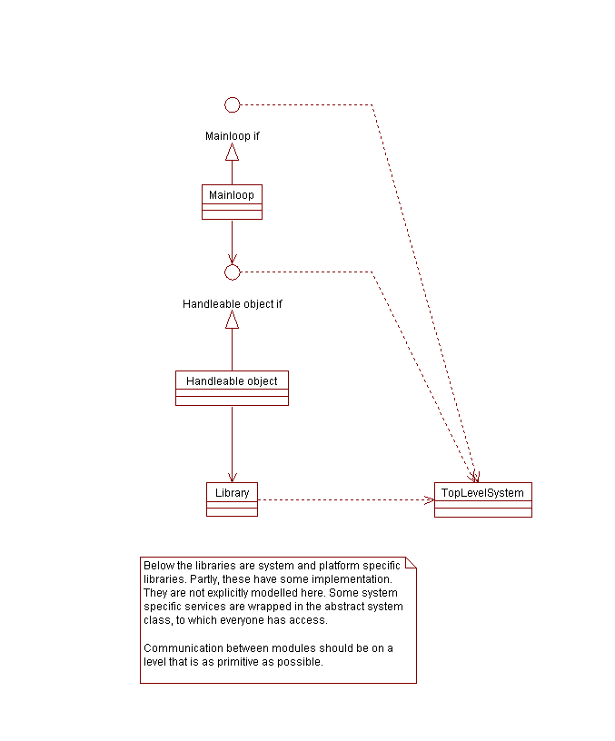 Figure 1: The relations between module types in Blender.
A more detailed view of this system is given in Figure 2. This view
presents several modules needed for making a complete Blender.
Figure 1: The relations between module types in Blender.
A more detailed view of this system is given in Figure 2. This view
presents several modules needed for making a complete Blender.
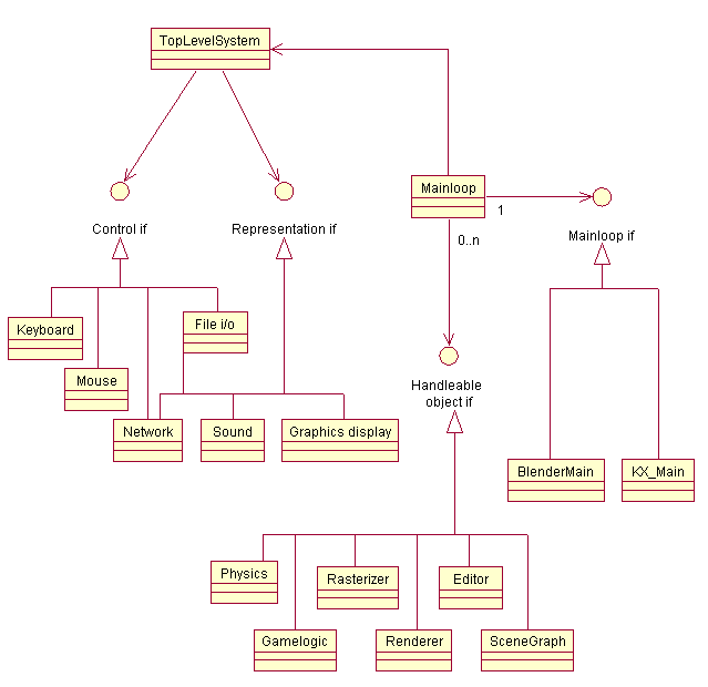 Figure 2: The relations between module types in Blender.
The implementation is centred around two instantiations of modules: a
system and a mainloop. The mainloop provides the coherence between the
functional modules. There may be more than one mainloop module in the
system, that can hand over control to each other. A dedicated
application only has one mainloop.
The system class act as a wrapper for the devices, and provides common
functionality, such as remembering command line options, global
variables, Making a new executable would typically consist of
selecting a set of functional modules and devices, and bind these
together with one or more mainloops, and a system class.
Figure 2: The relations between module types in Blender.
The implementation is centred around two instantiations of modules: a
system and a mainloop. The mainloop provides the coherence between the
functional modules. There may be more than one mainloop module in the
system, that can hand over control to each other. A dedicated
application only has one mainloop.
The system class act as a wrapper for the devices, and provides common
functionality, such as remembering command line options, global
variables, Making a new executable would typically consist of
selecting a set of functional modules and devices, and bind these
together with one or more mainloops, and a system class.
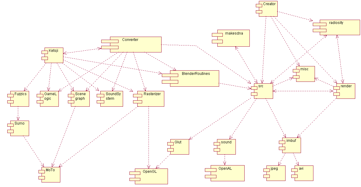 Figure 3: The current module interdependencies in Blender.
The migration to a new architecture can be facilitated if code chunks
can be recycled on component basis. Figure 4 shows the intermediary
model. Parallel development of modules will be possible if the
interfaces are concise, and stable. Designing such interface will be
the major task for the redesign.
Figure 3: The current module interdependencies in Blender.
The migration to a new architecture can be facilitated if code chunks
can be recycled on component basis. Figure 4 shows the intermediary
model. Parallel development of modules will be possible if the
interfaces are concise, and stable. Designing such interface will be
the major task for the redesign.
 Figure 4: The first intermediary structure target.