Transformation Constraint
This constraint is more complex and versatile than the other “transform” constraints. It allows you to map one type of transform properties (i.e. location, rotation or scale) of the target, to the same or another type of transform properties of the owner, within a given range of values (which might be different for each target and owner property). You can also switch between axes, and use the range values not as limits, but rather as “markers” to define a mapping between input (target) and output (owner) values.
So, e.g. you can use the position of the target along the X axis to control the rotation of the owner around the Z axis, stating that 1 unit along the target X axis corresponds to 10 units around the owner Z axis. Typical uses for this include gears (see note below), and rotation based on location setups.
Options
- Target
- Data ID used to select the constraints target, and is not functional (red state) when it has none.
- Extrapolate
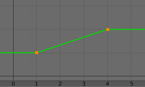
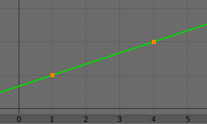
By default, the min and max values bound the input and output values; all values outside these ranges are clipped to them. When you enable this button, the min and max values are no longer strict limits, but rather “markers” defining a proportional (linear) mapping between input and corresponding output values. Let us illustrate that with two graphs Fig. The Extrapolate principles.. In these pictures, the input range (in abscissa) is set to (1.0 to 4.0), and its corresponding output range (in ordinate), to (1.0 to 2.0). The yellow curve represents the mapping between input and output.
The Extrapolate principles.
Source
It contains the input (from target) settings.
- Map From
The radio buttons allow you to select which type of property to use.
Location, Rotation, and Scale
- Mode (Rotation)
Allows specifying the type of rotation input to use, including different Euler orders, Quaternion, and other Rotation Channel Modes. Defaults to using the Euler order of the constraint owner.
In the Quaternion mode the channels are converted to weighted angles in the same way as the swing angles of the Swing and X/Y/Z Twist modes.
- From
- Independently for each axis (X, Y, and Z) the min and max number fields control the lower and upper bounds of the input value range. Note that if a min value is higher than its corresponding max value, the constraint behaves as if it had the same value as the max one.
- Source to Destination Mapping
- The three Axis Mapping selectors allow you to select which input axis to map to, respectively (from top to bottom), the X, Y and Z output (owner) axes.
Destination
It contains the output (to owner) settings.
- Map To
The three radio buttons allow you to select which type of property to control.
Location, Rotation, and Scale
- Order (Rotation)
- For rotation, allows specifying which Euler order to use during evaluation of the constraint. Defaults to using the order of the constraint owner.
- To
- The min and max number fields control the lower and upper bounds of the output value range, independently for each mapped axis. Note that if a min value is higher than its corresponding max value, the constraint behaves as if it had the same value as the max one.
- Mix
Specifies how the result of the constraint is combined with the existing transformation. The set of available choices varies based on the type of transformation.
- Replace
- The result of the constraint replaces the existing transformation.
- Multiply (Scale)
- The new values are multiplied with the existing axis values.
- Add (Location, Rotation)
- The new values are added to the existing axis values.
- Before Original (Rotation)
- The new rotation is added before the existing rotation, as if it was applied to a parent of the constraint owner.
- After Original (Rotation)
- The new rotation is added after the existing rotation, as if it was applied to a child of the constraint owner.
- Space
- Standard conversion between spaces.
Note
For historical reasons, the Mix mode defaults to Add for location and rotation, and Replace for scale.
When using the rotation transform properties of the target as input, whatever the real values are, the constraint will always “take them back” into the (-180 to 180) range. E.g. if the target has a rotation of 420 degrees around its X axis, the values used as X input by the constraint will be:
((420+180)modulo360)−180=60−...
This is why this constraint is not really suited for gears!
Similarly, when using the scale transform properties of the target as input, whatever the real values are, the constraint will always take their absolute values (i.e. invert negative ones).
When a min value is higher than its corresponding max one, both are considered equal to the max one. This implies you cannot create “reversed” mappings…

