Ocean Modifier
The Ocean modifier is a tool to simulate and generate a deforming ocean surface, and associated texture, used to render the simulation data. It is intended to simulate deep ocean waves and foam.
It is a port from the open source Houdini Ocean Toolkit.
Options
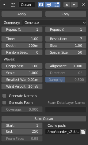
The Ocean modifier.
Geometry
- Geometry
- Generate
Creates a tiled mesh grid that exactly corresponds with the resolution of the simulation data.
When generating a mesh surface, the existing mesh object is completely overridden with the ocean grid. A UV channel is also added, mapping the (0.0 to 1.0) UV space to the simulation grid.
- Repeat X, Repeat Y
Controls the number of times the grid is tiled in X and Y directions. UVs for these tiled mesh areas continue outside of the (0.0 to 1.0) UV space.
- Displace
Uses the existing geometry rather than replacing it. Vertices are displaced along the local Z axis.
- Time
The time at which the ocean surface is being evaluated. To make an animated ocean, you will need to animate this value. The speed that the time value is changing will determine the speed of the wave animation.
- Depth
The constant depth of the ocean floor under the simulated area. Lower values simulate shallower waters by producing higher frequency details and smaller waves.
- Random Seed
A different seed will produce a different simulation result.
- Resolution
The main control of quality vs speed in the simulation engine. This determines the resolution of the internal 2D grids generated by the simulation.
The internal grids are powers of two of the resolution value, so a resolution value of
16, will create simulation data of size256×256. The higher the resolution, the more details will be produced, but the slower it will be to calculate.Note
When using the Generate modifier geometry option, this resolution value also determines the resolution of the generated mesh surface, equal to the resolution of the internal simulation data.
- Size
A simple scaling factor that does not affect the height of the waves or behavior of the simulation.
- Spatial Size
The width of the ocean surface area being simulated, in meters. This also determines the size of the generated mesh, or the displaced area. Of course, you can scale the object with the Ocean modifier in Object Mode to tweak the apparent size in your scene.
- Spectrum
Used to choose the wave spectrum model to use. Wave spectra are used to describe how energy moves through the waves at different frequencies. Energy travels through waves differently depending on the depth of the water and the wind speed.
- Turbulent Ocean
Use for turbulent seas with foam (Phillips).
- Established Ocean
Use for a large area, established ocean where the ocean would extend for miles with wind blowing for days allowing the waves to reach a point of equilibrium (Pierson-Moskowitz method).
- Established Ocean (Sharp Peaks)
Similar to regular Established Ocean however, waves will continue to grow with time creating sharper peaks (JONSWAP and Pierson-Moskowitz method). An extra parameter is used to define the sharpness of these peaks.
- Shallow Water
Use for shallow water with depths less than about 10 meters which makes it great for small lakes and ponds without heavy wind (JONSWAP and TMA – Texel-Marsen-Arsloe methods).
Examples of different spectra, settings adjusted for each.¶ 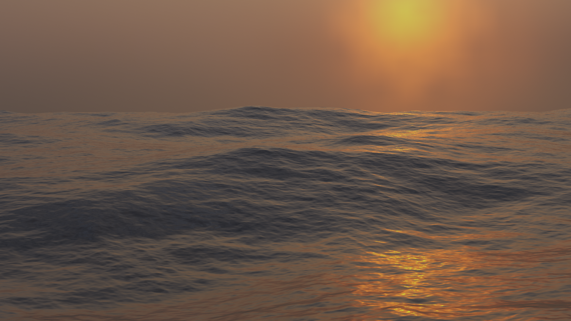
Turbulent Ocean.
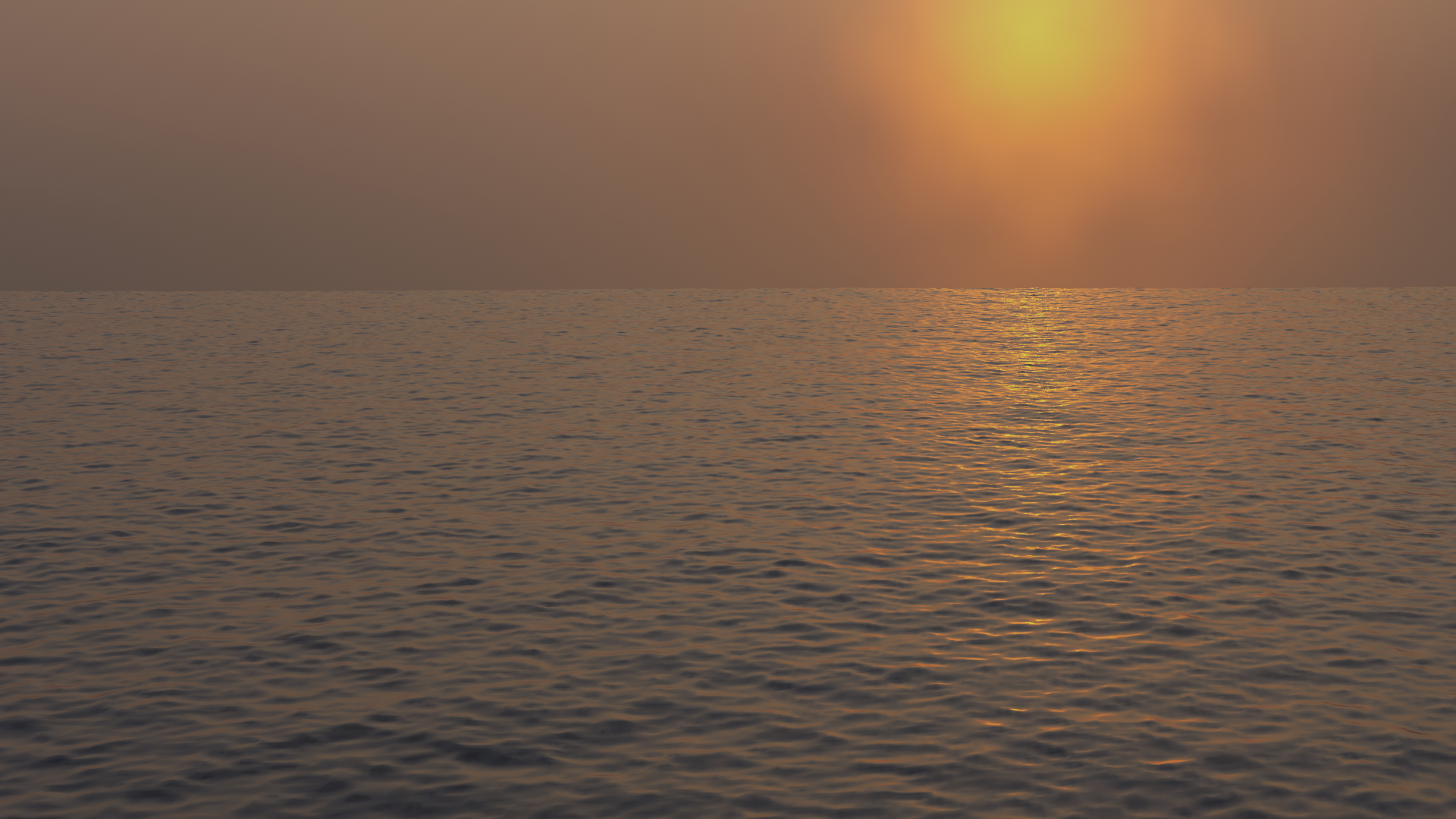
Established Ocean.
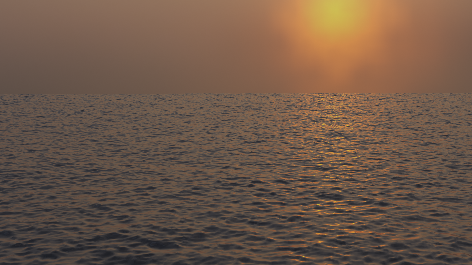
Established Ocean (Sharp Peaks).
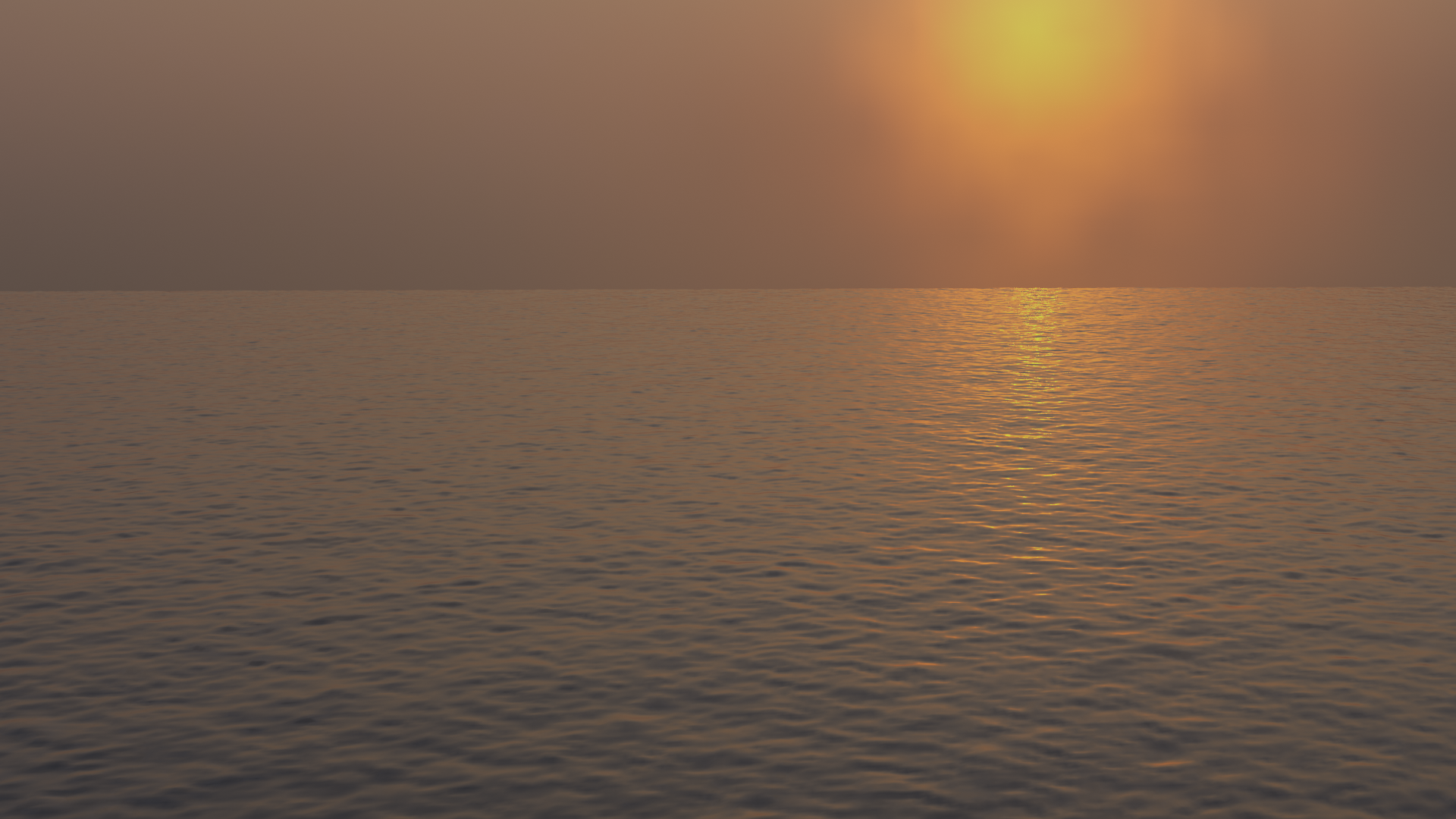
Shallow Water.
- Sharpness Peak
An artificial factor to control how sharp the peaks of the waves are in the Established Ocean (Sharp Peaks) and Shallow Water spectrum models.
- Fetch
Distance from a lee shore, called the fetch, or the distance over which the wind blows with constant velocity. Used by Established Ocean (Sharp Peaks) and Shallow Water spectrum models.
Wave
- Choppiness
The choppiness of the wave peaks. With a choppiness of 0, the ocean surface is only displaced up and down in the Z direction, but with higher choppiness, the waves are also displaced laterally in X and Y, to create sharper wave peaks.
- Scale
An overall scale control for the amplitude of the waves. It approximates the height or depth of the waves above or below zero.
Rather than just scaling the ocean object in Z, it scales all aspects of the simulation, displacement in X and Y, and corresponding foam and normals too.
- Alignment
The directionality of the wave shapes due to wind. At a value of 0, the wind and waves are randomly, uniformly oriented.
With higher Alignment values, the wind is blowing in a more constant direction, making the waves appear more compressed and aligned to a single direction.
- Direction
When using Alignment, the direction in degrees that the waves are aligned to (using local X axis as reference).
- Damping
When using Alignment, this will define the amount that inter-reflected waves are damped out. This has the effect of making the wave motion more directional (not just the wave shape).
With a Damping of 0.0, waves are reflected off each other in every direction, with a Damping of 1.0, these inter-reflected waves are damped out, leaving only waves traveling in the direction of the wind.
- Smallest Wave
A minimum limit for the size of generated waves. Acts similarly to a low-pass filter, removing higher frequency wave detail.
- Wind Velocity
Wind speed in meters/second. With a low velocity, waves are restricted to smaller surface waves.
Simulation Data Generation Options
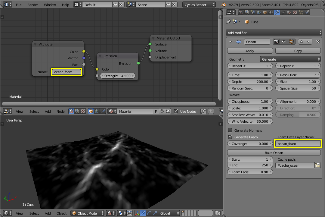
Using foam vertex colors with a named data layer.
By default, the simulator only generates displacement data, since it takes the least amount of work and gives the fastest feedback. Additional simulation data can be generated for rendering as well.
- Generate Normals
Simulates additional normal map data.
This can be used by the Ocean texture, when mapped to Normals, as a bump map, and enables generating normal map image sequences when baking.
- Generate Foam
Simulates additional foam data.
This can be retrieved by the Ocean texture for use in texturing (perhaps as a mask), and enables generating foam map image sequences when baking.
- Coverage
Tweaks the amount of foam covering the waves, negative values will reduce the amount of foam (leaving only the topmost peaks), positive values will add to it. Typically ranges from (-1.0 to 1.0).
- Foam Data Layer Name
Optional name for the vertex data layer, used by the Ocean Modifier to store foam maps as vertex colors. This is required for accessing the foam data in the renderer.
Baking
Rather than simulating the ocean data live, it can be baked to files in a given directory. When a simulation is baked, the simulator engine is completely bypassed, and the modifier/texture retrieves all information from the baked files.
Baking can be advantageous for a few reasons:
It is faster to use the stored data rather than re-calculating it.
It allows rendering of ocean data in external renderers.
It enables more advanced foam maps.
Data Files
Simulation data is stored as sequences of OpenEXR image maps,
one for each of displacement, normals, and foam (if enabled to be generated).
Upon loading the data from these baked files, when a frame of the bake sequence is read,
it is cached in memory. This means that accessing loaded frames subsequent times is fast,
not incurring the overhead of drive access.
Since these baked files are plain OpenEXR’s,
they can also be opened and rendered in any other application or renderer that supports them.
Baking Foam
Baking also provides improved foam capabilities. When simulating live, the ocean simulator retrieves data for that current frame only. In the case of the foam map, this represents the tips of wave crests for that given frame. In reality, after foam is created by wave interactions, it remains sitting on the top of the wave surface for a while, as it dissipates. With baking, it is possible to approximate that behavior, by accumulating foam from previous frames, leaving it remaining on the surface.
Baking Options
- Start, End
Frames of the simulation to bake (inclusive). The start and end frames of the bake are repeated when accessing frames outside of the baked range.
- Cache Path
Folder to store the baked EXR files in. The sequences will be in the form
disp_####.exr,normal_####.exr, andfoam_####.exr, where####is the four digit frame number. If the cache path folder does not exist, it will be created.
Simulation Internals
The simulator itself uses FFT methods to generate 2D grids of simulation information internally, very similar to 2D texture maps. The simulator can generate three types of data: displacement, normals, and extra data, that is used to calculate wave crest intersections (i.e. foam). After simulation, these maps are used to displace the ocean surface geometry in 3D, and also can be used for shading via the Ocean texture. The internal simulation engine is multi threaded with OpenMP to take advantage of multiple cores.
Examples
Simulated and baked to image maps in Blender, rendered in 3Delight.