PDT Examples
Example Models will be shown here, built Exclusively with PDT, Offset Edges and MeasureIt Add-ons.
This first one may not look too remarkable, except that it is totally accurate to dimensions, not approximately, taken from tracing a reference image.
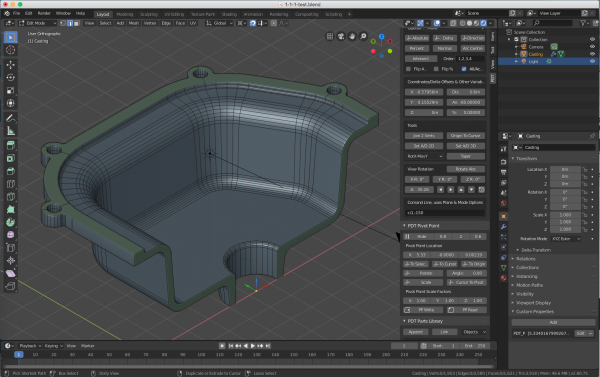
The draft angles on this half-casting are exactly 5 degrees, the length of sides between the radii are exactly to a dimension. All intersect points of faces have been placed accurately using PDT, not guessed from a zoomed in view. All fillets are exactly to a dimension and exactly in the right place.
Most of the accuracy of this model would be either impossible, or so very complicated, to achieve with Blender on its own. With PDT and Offset Edges, it was quick and easy to achieve this kind of topology, suitable for mechanical models, at a very high level of precision (constrained only by the storage of coordinates in Blender). You can also see the Pivot Point of this model, stored in its Custom Property.
Example 1 Construct a Casting:
Stage 1:
This example has been executed from the PDT Command Line section.
Set Move Mode to
Selected Entities.Place Vertex at 0,0,0 – Command na,,
Extrude 20 at 0 degrees – Command ei20, Working Plane set to
Front(X-Z)Place Cursor at fillet radius center. – Command ci22.5,90
Spin 85 Degrees – Blender Spin -85 degrees
Extrude 50 at 85 degrees – Command ei50,85
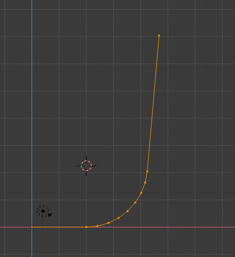
Stage 2:
Duplicate first Vertex 150 in X 100 in Z – Command dd150,,100
Extrude 100 at 180 degrees – Command ei100,180
Intersect Corner –
Operation=Move, All/Active Selected, clickIntersectExtrude 100 in Y – Command – ei100,90 Working Plane set to
Top(X-Y)Bevel Corner – Blender Command Bevel, 25mm
Offset Edges 2.5 – Offset Edges Extrude Command.
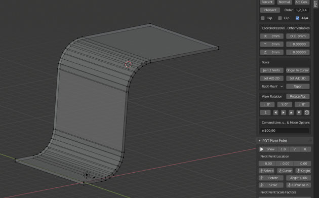
Stage 3:
Spin in Top View – Blender Spin Command, 62.5 degrees
Extrude 47.5 at 27.5 degrees – Command ei47.5,27.5
Spin in Top View – Blender Spin Command, 27.5 degrees
Extrude 30 at 0 degrees – Command ei30,
Complete highlighted faces using standard Blender techniques to get this:
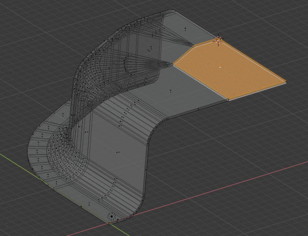
Then simply extrude the two front face corners level with the cursor in X and then selected vertices to make the faces with F key.
This model is accurate to dimensions, draft angles and corner radii.
All the command line inputs could be replaced by using the Operation
options and Command buttons instead.
Optionally, to improve topology, one could rationalize the top faces to this:
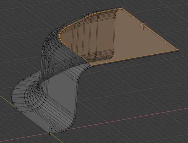
It would depend on what we wanted to do ultimately with the top faces, like maybe cut holes in them.
Example 2 - Modify a Hydraulic Cylinder:
Take this mesh, we have no idea at what angle the mesh lies, since it was drawn to a delta measurement not a directional measurement:
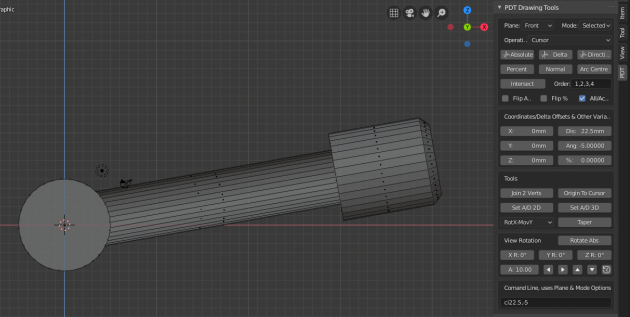
We now want to make it longer along the angle at which it lies, by a known amount,
so we first use the Set A/S 2D tool to set the angle:
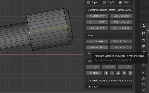
You can see the angle was 9.9935 degrees, we then input the distance we require in the Distance input box,
set Operation to Move and click the Direction command to get this:
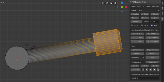
You can see the selected vertices have been moved exactly 3000mm at exactly 9.9935 degrees. This is one of the main reasons why PDT exists, to do just this type of precise alteration of geometry.