Worked Example - Building A Book Scanner
In this page we will show how to make complex parts of this book scanner using PDT.
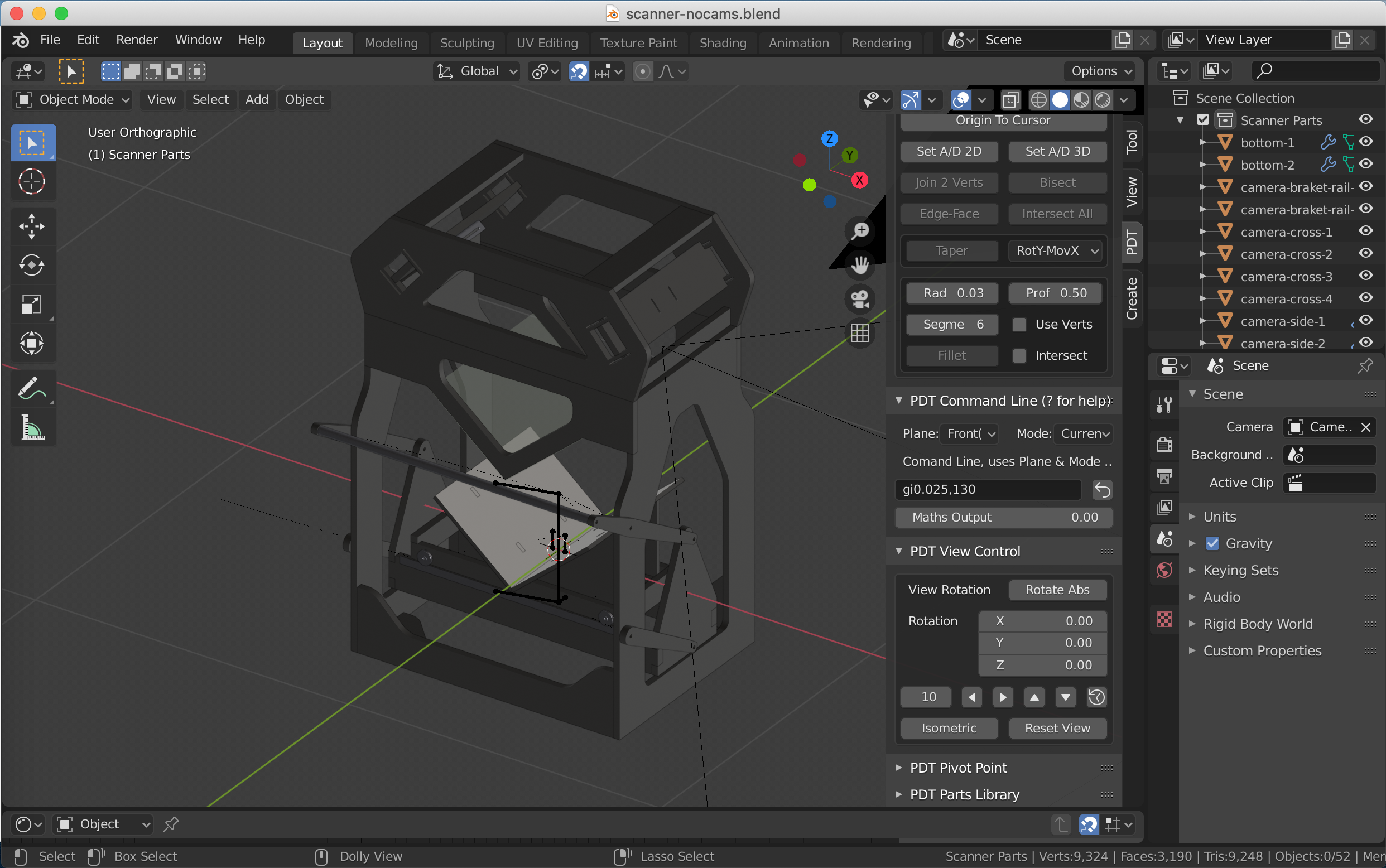
This is considered a typical CAD design and consists of many parts that can be made by extruding a profile to make the 3D mesh. It should be noted that this is a preferred manner to work in the CAD environment, rather than starting with a 3D mesh and carving bits out of it. We will start with a component that has a hole in it so that process is explained properly.
Making the End Panels.
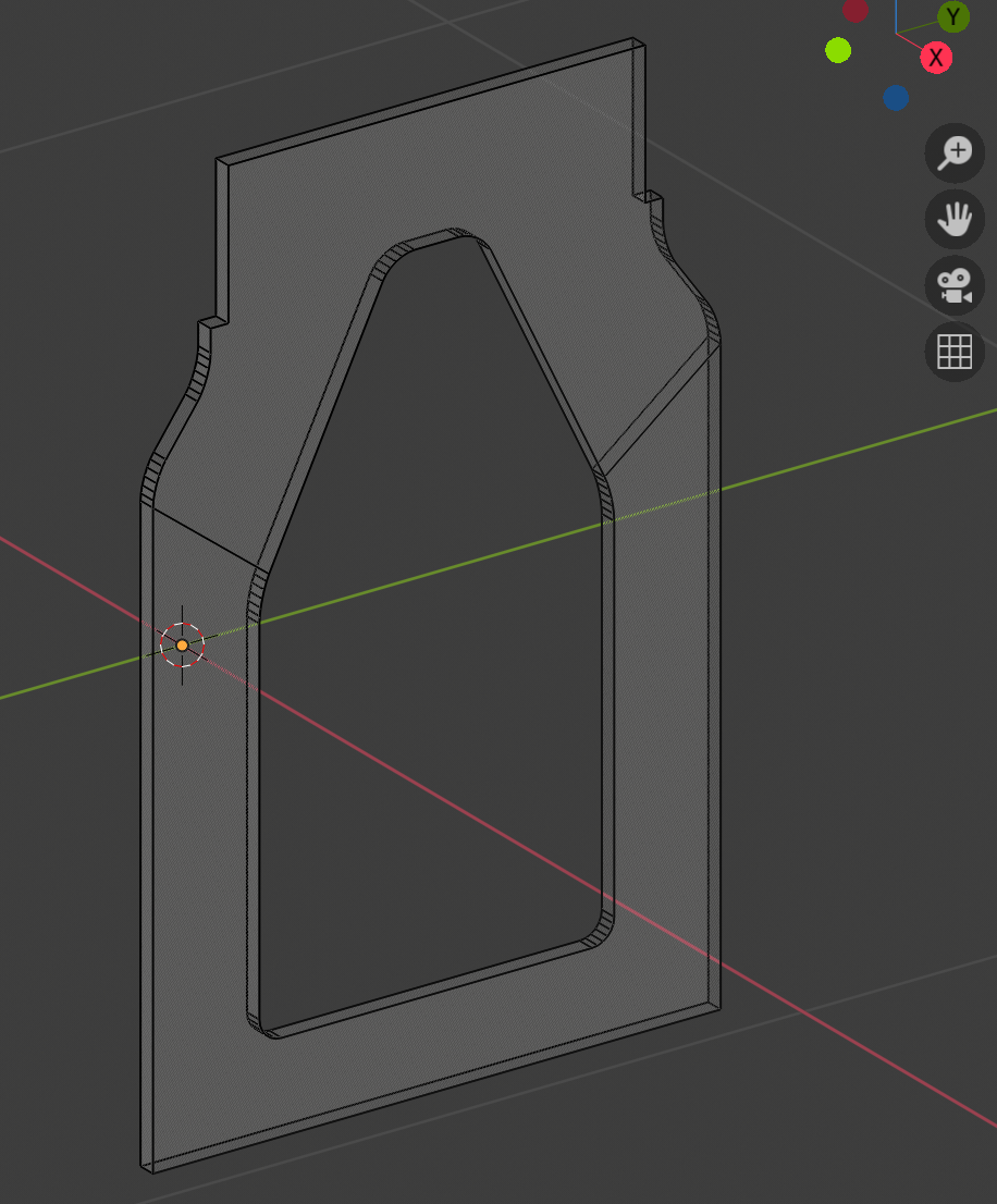
The End Panel in Edit Mode
For this we will start with a single vertex object at 0,0,0 (You will need to load the “Extra Objects” Add-on).
I placed all objects, apart from the wheels at the World Centre for ease, so the start point for this component is 0.39,-0.32,-0.3. The first thing to do therefore is move this single vertex in Edit mode to that location. For this there are two choices:
Set Cartesian Coordinates to 0.39,-0.32,-0.3 respectively, set operation to
Moveand clickDelta.OR Key gd0.39,-0.32,-0.3 into Command Line.
Now we need to extrude this vertex 0.64 in Y:
Set Cartesian Coordinates to 0,0.64,0 respectively, set operation to
Extrude Verticesand clickDelta.OR Key vd,0.64, into Command Line.
Select both vertices and extrude 0.7 in Z:
Set Cartesian Coordinates to 0,0,0.7 respectively, set operation to Extrude Vertices and click
Delta.OR Key vd,,0.7 into Command Line.
Copy leftmost of the new vertices 0,0.65,0.14:
Set Cartesian Coordinates to 0,0.65,0.14 respectively, set operation to
Duplicate Geometryand clickDelta.OR Key dd,0.65,0.14 into Command Line.
Extrude new vertex -0.04 in Z:
Set Cartesian Coordinates to 0,0,-0.04 respectively, set operation to
Extrude Verticesand clickDelta.OR Key vd,,0.04 into Command Line.
You should now have this:
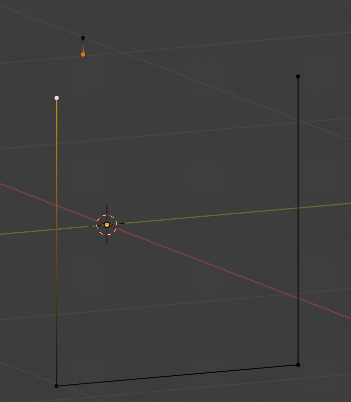
I have selected two vertices, join these two together with Join 2 Verts Tool.
Select Top Left vertex and extrude it 0.02 in Y:
Set Cartesian Coordinates to 0,0.02,0 respectively, set operation to
Extrude Verticesand clickDelta.OR Key vd,0.02, into Command Line.
Extrude 0.16 in Z:
Set Cartesian Coordinates to 0,0,0.16 respectively, set operation to
Extrude Verticesand clickDelta.OR Key vd,,0.16 into Command Line.
You should now have this:
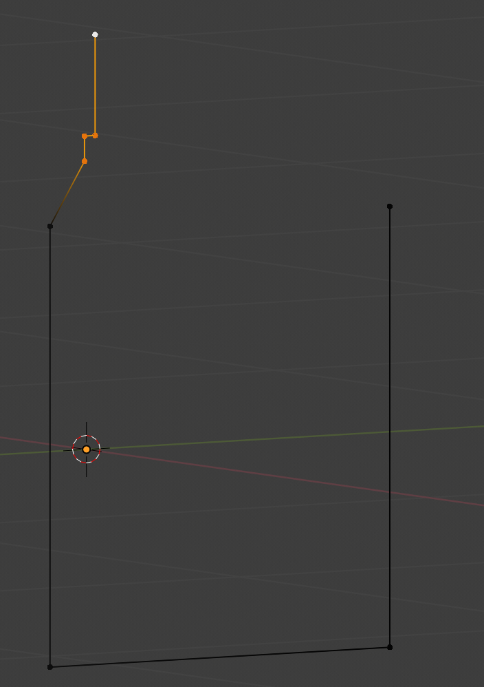
Duplicate the selected vertices to the other side:
Set 3D Cursor, SHIFT+D, CTRL+M Y - standard Blender commands.
Join the gaps using Join 2 Verts and you get this:
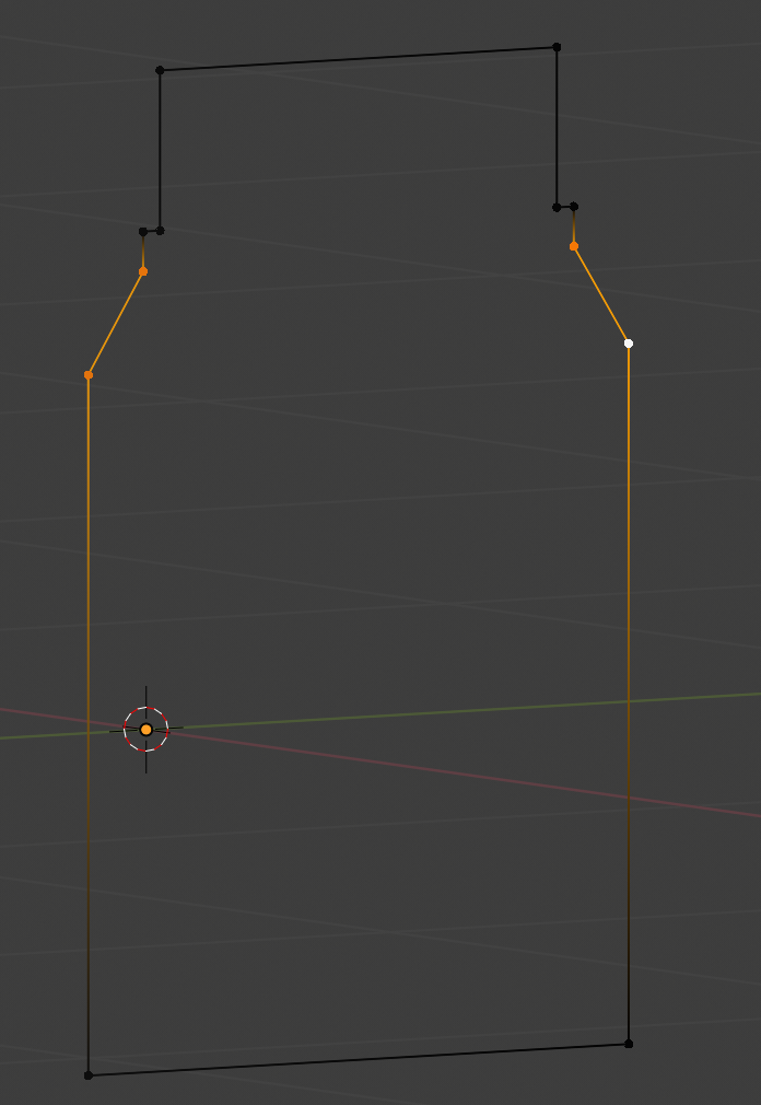
Select the vertices shown, they need filleting:
Set
Radiusto 0.03,Profileto 0.5 andSegmentsto 6, clickFillet.OR Key fv0.03,6,0.5 into Command Line.
This is the result:
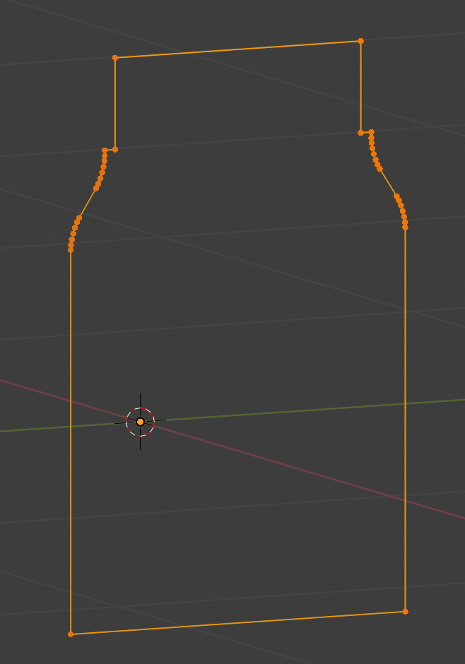
Copy bottom left vertex 0.12 in Y & 0.1 in Z:
Set Cartesian Coordinates to 0,0.12,0.1 respectively, set operation to
Duplicate Geometryand clickDelta.OR Key dd,0.12,0.1 into Command Line.
Extrude 0.45 in Z:
Set Cartesian Coordinates to 0,0,0.45 respectively, set operation to
Extrude Geometryand clickDelta.OR Key vd,,0.45 into Command Line.
Extrude 0.15 in Y, 0.31 in Z:
Set Cartesian Coordinates to 0,015,0.31 respectively, set operation to
Extrude Geometryand clickDelta.OR Key vd,0.15,0.31 into Command Line.
Duplicate these new vertices to the other side:
Set 3D Cursor, SHIFT+D, CTRL+M Y - standard Blender commands.
Join the gaps using Join 2 Verts and you get this:
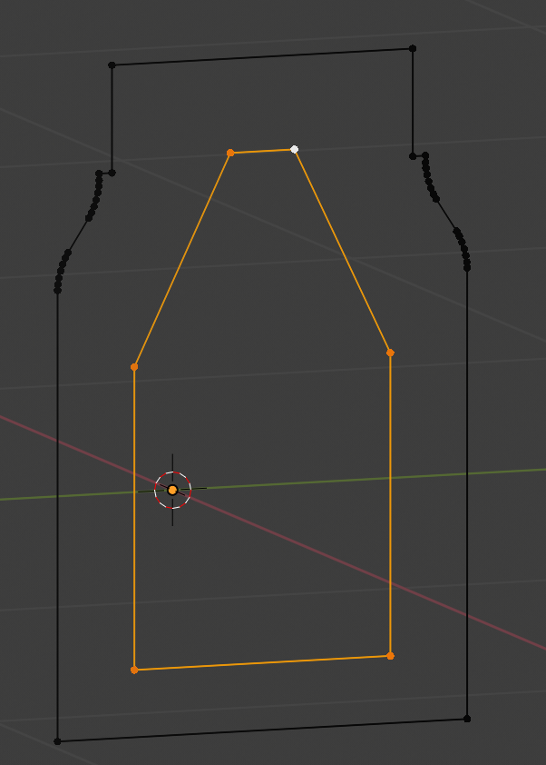
Select the vertices shown, they need filleting:
Set
Radiusto 0.03,Profileto 0.5 andSegmentsto 6, clickFillet.OR Key fv0.03,6,0.5 into Command Line.
You should now have this:
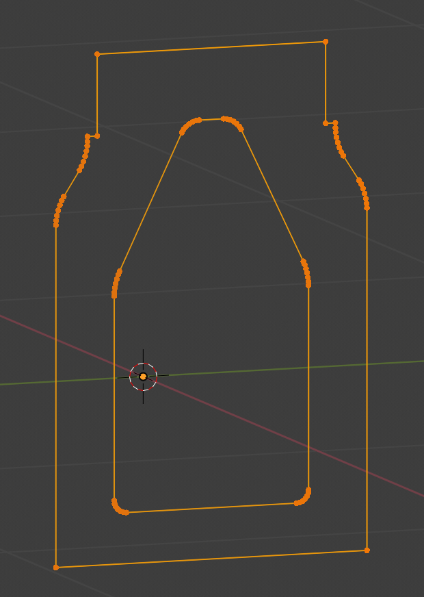
Join these two vertices each side using Join 2 Verts Tool giving this:
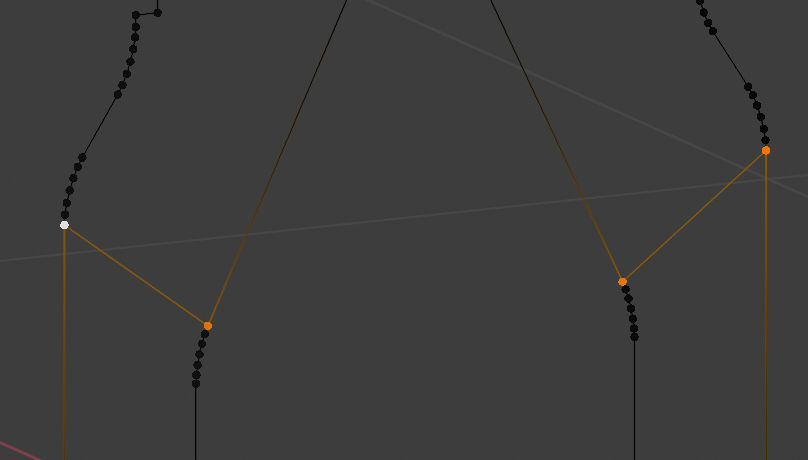
Select these vertices and key F - (Blender Face command) to give this:
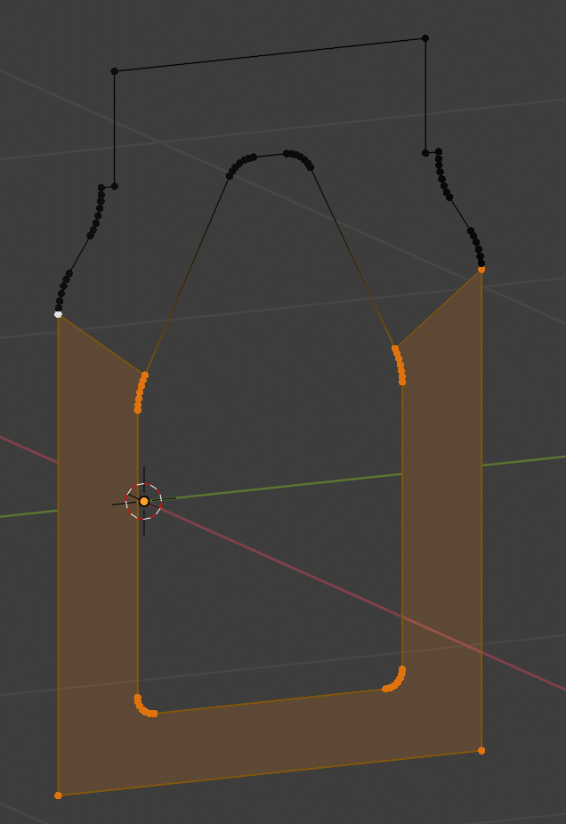
Switch selection (CTRL+I), select four vertices across joins and make Face again giving this:
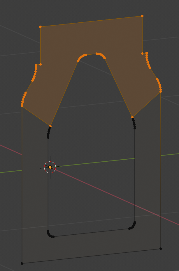
Duplicate entire geometry -0.02 in X:
Set Cartesian Coordinates to -0.02,0,0 respectively, set operation to
Duplicate Geometryand clickDelta.OR Key dd-0.02,, into Command Line.
You should now have this:
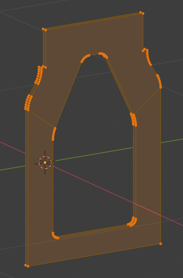
Select both outer edge rings and choose Edge => Bridge Edge Loops,
repeat for inner edge loops to get all the faces:
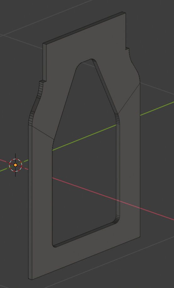
_hown in Face Mode
Exit Edit Mode, name object “End-R” and duplicate Object (SHIFT+D), rename this new object “End-L”.
Edit new “End-L” Object and mirror all faces about X Axis.
Set 3D Cursor.
Select All Geometry.
Key CTRL+M.
Key SHIFT+N to normalise faces.
You should now have two ends like this:
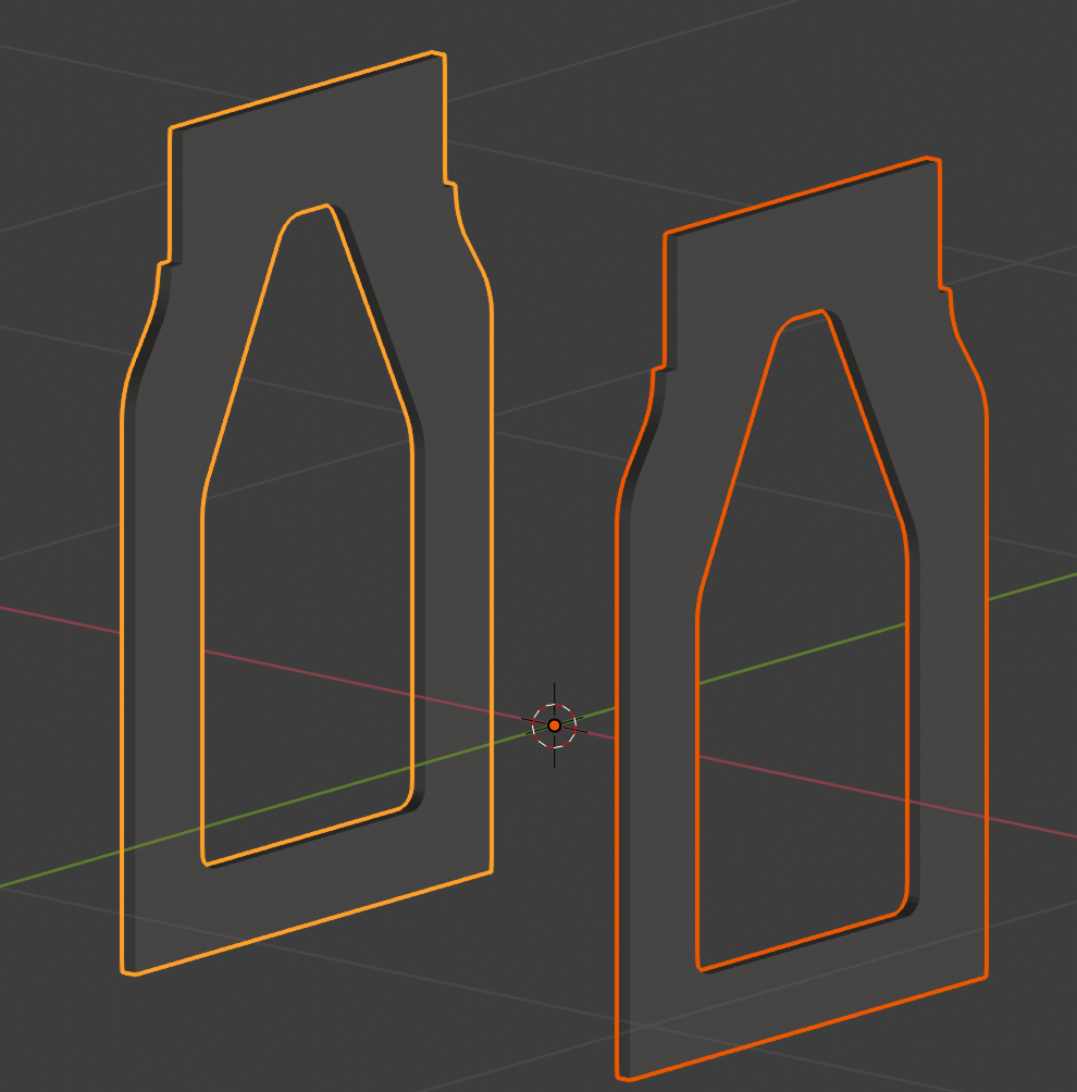
You should be able to see the advantages of making end profiles, then bridging the edge loops to make an extruded shape. This avoids duplicated geometry and also allows for holes in the object by making faces that split across the hole. I would then add an Edge Modifier to the objects to clean up the shading and of course make a suitable material.
You can also see that we can either use PDT Design Functions & Tools,
or use PDT Command Line to just type in the commands.
We can use the same principles to make all the other components.
_To Be Continued…_