Design Tools#
The Menu for PDT Tools:
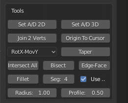
This section of the menu deals with the Tools, which work with their own variables, in some cases, they also use the Working Plane.
Set A/D 2D:#
This button is used to measure the angle relative to horizontal in the Working Plane subtended by two vertices,
or two objects. You can see a full list of available options in the table on the previous page (Before You Begin)
for both Edit and Object modes.. Here the Working Plane setting is important, because, if set to View,
the output will be calculated relative to the views local axes, however the view is oriented,
otherwise it works with the global axes for the view.
Output: Sets the Distance, Angle, X, Y & Z input variables.
Selection: in Edit Mode select two vertices with your mouse, the Active vertex is considered to be the center of rotation, or fulcrum point. In Object Mode the Active object is similarly considered.
Example 1: Set the Input variables to two vertices in Edit Mode in Front view,
set Working Plane to Front, select the rotational vertex, select the center vertex.
The Distance variable is set to the apparent separation fo the two vertices in the front view,
the Angle is set to the apparent angle relative to horizontal in the front view, the X, Y & Z
inputs are set to the delta offset between the two vertices in the view axes.
Example 2: Set the Input variables to two objects in Object Mode in Top view,
set Working Plane to Top(X-Y), select the rotational object, select the center object.
The Distance variable is set to the apparent separation of the two objects in the top view,
the Angle is set to the apparent angle relative to horizontal in the top view, the X, Y & Z
inputs are set to the delta offset between the two vertices in the view axes.
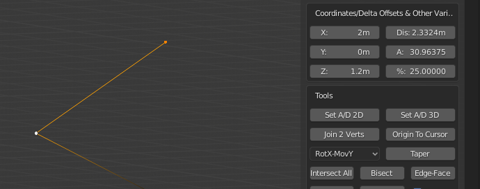
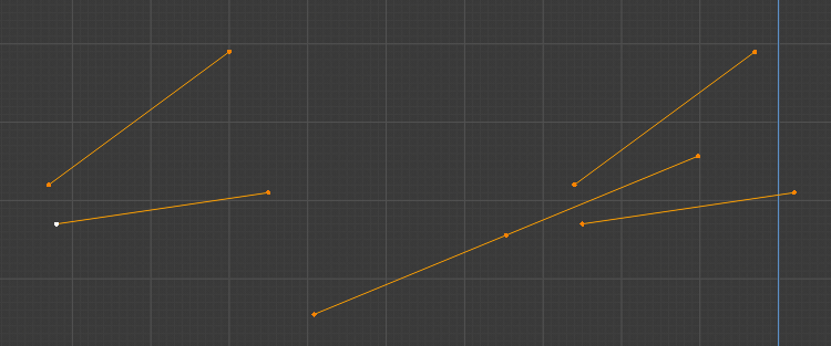
Parameters set from two Vertices in Front Working Plane.
Set A/D 3D:#
This button is used to measure the angle subtended by three vertices, or three objects.
You can see a full list of available options in the table on the previous page (Before You Begin)
for both Edit and Object modes. Here the Working Plane
setting is irrelevant because the angle is calculated in 3D space.
Output: Sets the Distance, Angle, X, Y & Z input variables.
Selection: in Edit Mode select three vertices with your mouse, the Active vertex is considered to be the center of rotation, or fulcrum point. In Object Mode the Active object is similarly considered.
Example 1: Set the Input variables to three vertices in Edit Mode, select the two rotational vertices, select the center vertex. The Distance variable is set to the real separation of the first vertex and center vertex in the front view, the Angle is set to the real angle between the three vertices, X, Y & Z inputs are set to the delta offset between the first and center vertices.
Example 2: Set the Input variables to three objects in Object Mode, select the two rotational objects, select the center object. The Distance variable is set to the real separation of the first vertex and center vertex in the front view, the Angle is set to the real angle between the three vertices, X, Y & Z inputs are set to the delta offset between the first and center objects.
Join 2 Vertices:#
This button is used to join two disconnected vertices that do not form part of the same face.
You can see a full list of available options in the table on the previous page (Before You Begin)
for both Edit and Object modes. Here the Working Plane setting is irrelevant.
This Tool works only in Edit Mode.
Selection: Select two vertices by any method.
Example 1: Join two vertices, select two vertices that do not form part of the same face.
If the vertices do form part of the same face you should use the standard Blender Join command (hotkey j).
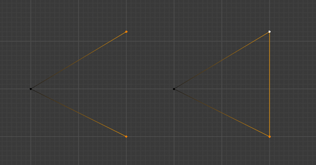
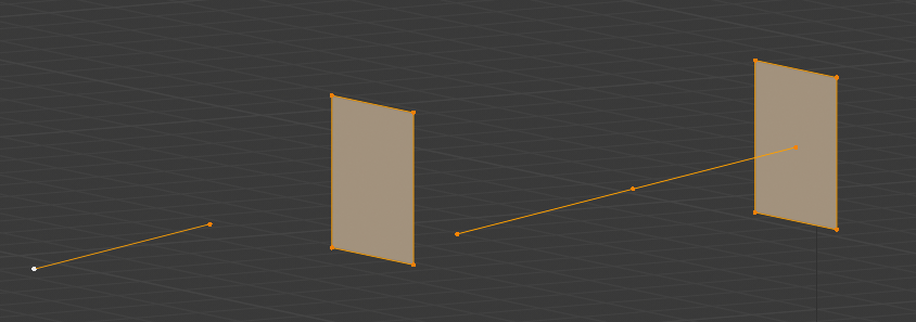
The two Vertices have been joined to form, in this case, a Closed Loop, Before on the Left, After on the Right.
Origin To Cursor:#
This button is used to set the Object Origin to the current Cursor location.
You can see a full list of available options in the table on the previous page
(Before You Begin) for both Edit and Object modes. Here the Working Plane
setting is irrelevant. This Tool works in Edit & Object Modes.
Selection: None required in Edit Mode, select one object in Object Mode.
Example 1: Set Object Origin to 1,3,2 in Edit Mode, set X, Y & Z inputs to 1,3,2 respectively,
set Operation to Cursor, click Absolute button to move cursor. Click Origin To Cursor Tool,
Origin is moved, but geometry is not moved from its absolute position in World Space.
Taper:#
This button is used to taper one face of an object, by rotating selected vertices about a fulcrum point, whilst maintaining the projection of associated edges, to a predefined angle. You can see a full list of available options in the table on Page 3 of this Wiki for both Edit and Object modes. Here the Working Plane setting is irrelevant. This Tool works only in Edit Mode.
Uses: Move/Rot Axis Selector.
Selection: Select vertices to be moved, then select fulcrum vertex with SHIFT+Mouse, active vertex is considered the rotational center.
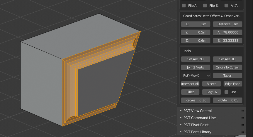
Example 1: Taper the end of a cube in front view - 25 degrees,
set Angle to -25 degrees (25 degrees clockwise), select all vertices to be tapered,
SHIFT+Mouse select center of rotation point vertex, set Move/Rot selector to RotY,MovX,
set Working Plane to Front(X-Z), click Taper.
The significance of RotY,MovX is that the Y axis is used as the rotation axis
and vertices will be moved along the X axis, in View Working Plane Mode,
remember these are then Local axes, not Global ones.
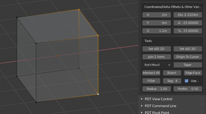
Before, the face is at 90 degrees to horizontal.
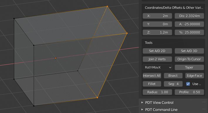
After the face is now at 65 degrees to horizontal.
Intersect All:#
This button is used to cut edges at any point they intersect with other selected edges.
You can see a full list of available options in the table on the previous page
(Before You Begin) for both Edit and Object modes. Here the Working Plane
setting is irrelevant. This Tool works only in Edit Mode.
Selection: Select a set of Edges by any method.
Example 1: Cut a set of edges at every point where they overlap, or intersect,
select required edges, click Intersect All button.
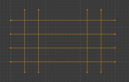
Selected Edges Before.
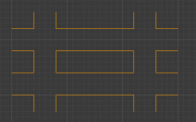
Selected Edges After, some have been removed.
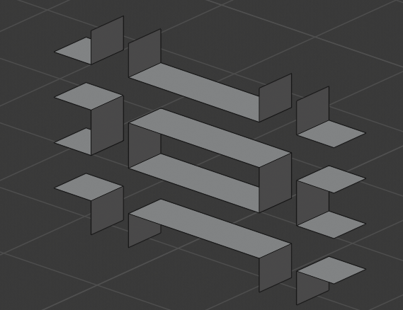
Selected Edges After Extrusion.
Bisect:#
This button is used to form a Bisecting Edge between two other co-planar edges.
You can see a full list of available options in the table on the previous page
(Before You Begin) for both Edit and Object modes. Here the Working Plane
setting is irrelevant. This Tool works only in Edit Mode.
Selection: Select two Edges by any method.
Example 1: Bisect two edges, select 2 co-planar edges, click Bisector button.
Bisected Edges, Before on Left, After on Right, you can see both Bisectors have been drawn.
Edge To Face:#
This button is used to project an edge to its intersection with a disconnected face.
You can see a full list of available options in the table on the previous page
(Before You Begin) for both Edit and Object modes. Here the Working Plane
setting is irrelevant. This Tool works only in Edit Mode.
Selection: Select only one edge and one disconnected face.
The intersection point need to lie within the area of the face.
Example 1: Extend one edge to a disconnected face, select one edge and one face, click Edge To Face.
Edge Extended, Before on Left, After on Right.
Fillet:#
This button is used to fillet the corners of geometry, either closed edge loops, or edges.
You can see a full list of available options in the table on the previous page
(Before You Begin) for both Edit and Object modes. Here the Working Plane
setting is irrelevant. This Tool works only in Edit Mode.
Uses: Radius, Segments & Profile inputs & Use Vertices checkbox.
Selection: Any number of vertices, or edges by any method.
The Profile settings is the same as for Blender Bevel command, i.e. ranges from 0 to 1, 0.05 is a convex fillet, 0.5 is a concave fillet.
Example 1: Fillet a closed loop of edges at each corner radius 0.5, 6 segments,
profile 0.5, select corner vertices to be filleted, set Radius to 0.5,
set Segments to 6, set Profile to 0.5, check Use Vertices.
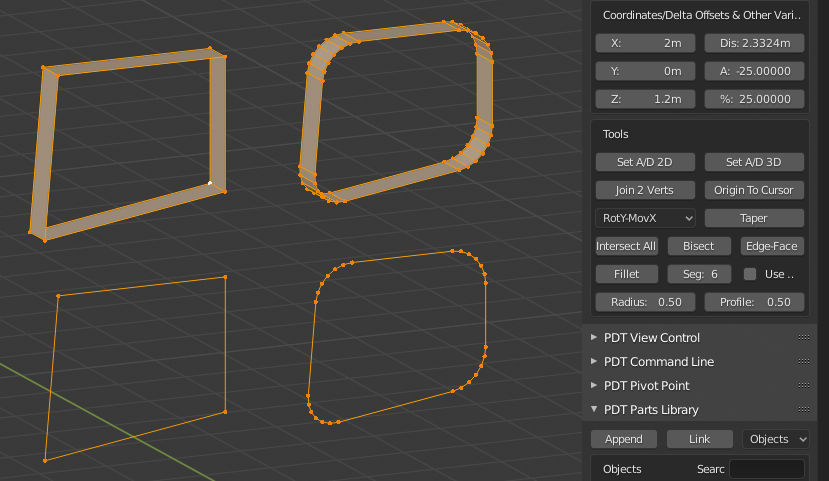
The image shows two Before and Afters, in the bottom set Use Vertices was checked, in the top set it was not, this is how to fillet edges.
Another Before and After, you can see the settings used to produce this.
Tip! Using an even number of segments will result in better topology (no tris) where three bevels meet at 90 degree offsets, for example.
Note! From version 1.1.8 the Fillet Tool now has an Intersect checkbox.
When this is activated the toll will accept only two non-connected edges,
or four vertices representing two non-connected edges. These two edges and first intersected,
then the intersection vertex is filleted. The Use Verts
checkbox is ignored in this mode of operation. Should these two edges
not intersect in the Working Plane, an error is returned.
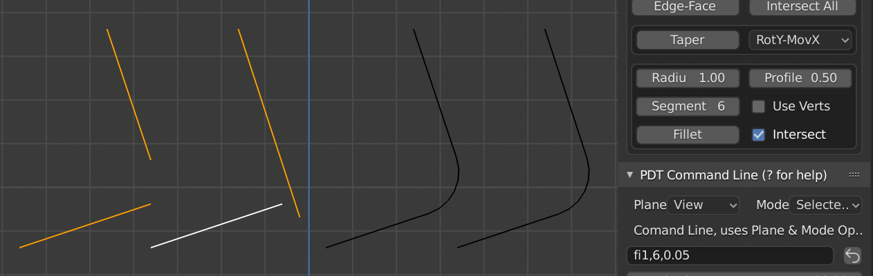
Two examples of Before on the Left and After on the Right.