Introduction
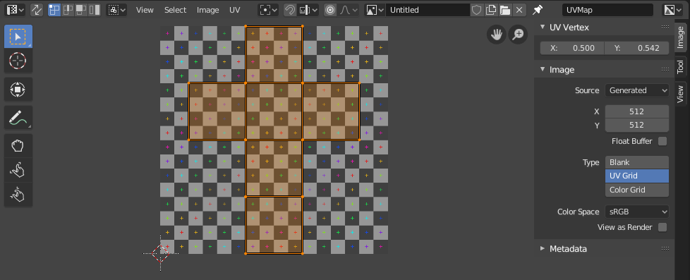
The UV Editor is used to map 2D assets like images/textures onto 3D objects and edit what are called UVs.

UV Editor with a UV map and a test grid texture.
The most flexible way of mapping a 2D texture over a 3D object is a process called «UV mapping». In this process, you take your three-dimensional (X, Y & Z) mesh and unwrap it to a flat two-dimensional (X & Y … or rather, as we shall soon see, «U & V») image. Colors in the image are thus mapped to your mesh, and show up as the color of the faces of the mesh. Use UV texturing to provide realism to your objects that procedural materials and textures cannot do, and better details than Vertex Painting can provide.
UVs Explained
The best analogy to understanding UV mapping is cutting up a cardboard box. The box is a three-dimensional (3D) object, just like the mesh cube you add to your scene.
If you were to take a pair of scissors and cut a seam or fold of the box, you would be able to lay it flat on a tabletop. As you are looking down at the box on the table, we could say that U is the left-right direction, and V is the up-down direction. This image is thus in two dimensions (2D). We use U and V to refer to these «texture-space coordinates» instead of the normal X and Y, which are always used (along with Z) to refer to the three-dimensional space (3D).
When the box is reassembled, a certain UV location on the paper is transferred to an (X, Y, Z) location on the box. This is what the computer does with a 2D image in wrapping it around a 3D object.
During the UV unwrapping process, you tell Blender exactly how to map the faces of your object (in this case, a box) to a flat image in the UV Editor. You have complete freedom in how to do this. (Continuing our previous example, imagine that, having initially laid the box flat on the tabletop, you now cut it into smaller pieces, somehow stretch and/or shrink those pieces, and then arrange them in some way upon a photograph that is also lying on that tabletop.)
Example

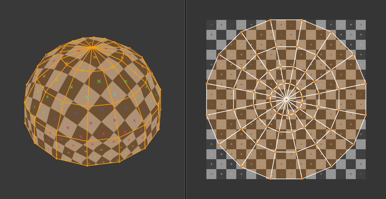
3D space (XYZ) versus UV space.
In this image you can easily see that the shape and size of the marked face in 3D space is different in UV space. This difference is caused by the «stretching» (technically called mapping) of the 3D part (XYZ) onto a 2D plane (i.e. the UV map).
If a 3D object has a UV map, then, in addition to the 3D coordinates X, Y, and Z, each point on the object will have corresponding U and V coordinates.
Obs
On more complex models (like seen in the sphere above) there pops up an issue where the faces cannot be cut, but instead they are stretched in order to make them flat. This helps making easier UV maps, but sometimes adds distortion to the final mapped texture.
Advantages of UVs
While procedural textures are useful – they never repeat themselves and always «fit» 3D objects – they are not sufficient for more complex or natural objects. For instance, the skin on a human head will never look quite right when procedurally generated. Wrinkles on a human head, or scratches on a car do not occur in random places, but depend on the shape of the model and its usage. Manually-painted images, or images captured from the real world gives more control and realism. For details such as book covers, tapestry, rugs, stains, and detailed props, artists are able to control every pixel on the surface using a UV texture.
A UV map describes what part of the texture should be attached to each polygon in the model. Each polygon’s vertex gets assigned to 2D coordinates that define which part of the image gets mapped. These 2D coordinates are called UVs (compare this to the XYZ coordinates in 3D). The operation of generating these UV maps is also called «unwrap», since it is as if the mesh were unfolded onto a 2D plane.
For most simple 3D models, Blender has an automatic set of unwrapping algorithms that you can easily apply. For more complex 3D models, regular Cubic, Cylindrical or Spherical mapping, is usually not sufficient. For even and accurate projection, use seams to guide the UV mapping. This can be used to apply textures to arbitrary and complex shapes, like human heads or animals. Often these textures are painted images, created in applications like the Gimp, Krita, or your favorite painting application.
Interface
Header

UV Editor header.
The header contains several menus and options for working with UVs.
- Sync Selection
Syncs selection between the UV Editor and the 3D Viewport. See Sync Selection for more details.
- Selection Mode
The UV element type to select. See Selection Mode for more details.
- Sticky Selection Mode
Option to automatically expand selection. See Sticky Selection Mode for more details.
- View
Tools for controlling how the content is displayed in the editor. See Navigating.
- Select
Tools for Selecting UVs.
- Image
Tools for opening and manipulating images. See Editing.
- UV
Contains tools for Unwrapping Meshes and Editing UVs.
- Image
A data-block menu used for selecting images. When an image has been loaded or created in the Image editor, the Image panel appears in the Sidebar region. See Image Settings.
- Image Pin
Todo.
- Active UV Loop Layer
Select which UV map to use.
- Viewport Gizmos
- Selectively show or hide specific gizmo controls that are displayed in the 2D viewport.
All gizmos can be hidden or shown at once with the toggle next to the pop-over arrow.
- Navigate
Enable/disable the gizmos used to pan or zoom the 2D viewport, see Navigation Gizmos for more information.
- Display Channels
Select what color channels are displayed.
- Color & Alpha:
Replaces transparent pixels with background checkerboard, denoting the alpha channel.
- Color:
Display the colored image, without alpha channel.
- Alpha:
Displays the Alpha channel a grayscale image. White areas are opaque, black areas have an alpha of 0.
- Z-Buffer:
Display the depth from the camera, from Clip Start to Clip End, as specified in the Camera settings.
- Red, Green, Blue:
Single Color Channel visualized as a grayscale image.
Tool Settings
- Pivot
Similar to working with pivot points in the 3D Viewport.
- UV Snapping
Controls to snap UV points, similar to snapping in the 3D Viewport.
- Proportional Editing
See Proportional Editing.