The Armature Object
Relevant to Blender v2.31
The armature Object is the key Object of character animation. It is an object comprising several interconnected or not interconnected "bones". A series of interconnected bones is an "Inverse Kinematics (IK) Chain" or simply "Chain" of bones. An IK Chain is something more complex than a standard Parent relation inasmuch not only the movements of the "Parent" bone are transmitted to the children, but also the movements of the last child of the chain can transmit up in the chain to the parent bone if an Inverse Kinematics solution is asked for. Bones can be moved as if they were a set of rigid, undeformable Object with perfect joints. Consider an armature to be like a skeleton for a living creature. The arms, legs, spine and head are all part of the same skeleton object.
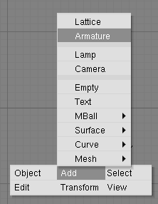
To create a new armature, select SPACE>>Add>>Armature from the Toolbox (Figure 3). A new bone will appear with its root at the location of the 3D cursor. As you move the mouse, the bone will resize accordingly. LMB will finalize the bone and start a new one that is the child of the previous one. In this way you can make a complete chain. Pressing ESC will cancel the addition of the bone.
You can add another bone to an armature while it is in Edit Mode with SPACE>>Add>>Armature from the toolbox again. This will start the bone-adding mode again, and the new bones you create will be a part of the current armature but will form a separate chain.
You can also extrude bones from existing bones by selecting a bone joint and pressing EKEY. The newly created bone will be a child of the bone it is extruded from, but not of its IK chain.
While in Edit Mode, you can perform the following operations to the bones in an armature.
Adjusting - Select one or more bone joints and use any of the standard transformation operations to adjust the position or orientation of any bones in the armature. Note that IK chains cannot have any gaps between their bones and as such moving the end point of a bone will move the start point, or root of its child.
You can select an entire IK chain at once by moving the mouse cursor over a joint in the chain and pressing LKEY. You can also use the boundary select tool (BKEY).
Deleting - You can delete one or more bones by selecting its start and end points. When you do this you will notice the bone itself will be drawn in a highlighted colour. Pressing XKEY will remove the highlighted bones. Note that selecting a single point is not enough to delete a bone.
Point Snapping - It is possible to snap bone joints to the grid or to the cursor by using the snap menu accessible with SHIFT-S.
Numeric Mode - For more precise editing, pressing NKEY will bring up the numeric entry box. Here you can adjust the position of the start and end points as well as the bone's roll around its own axis.
An easy way to automatically orient the z-axis handles of all selected bones (necessary for proper use of the pose-flipped option) is to press CTRL-N. Remember to do this before starting to create any animation for the armature.
Undo - While in Edit Mode, you can cancel the changes you have made in the current editing session by pressing UKEY. The armature will revert to the state it was in before editing began.
It is also possible to join two Armatures together into a single Object. To do this, ensure you are in Object Mode, select both armatures and press CTRL-J.
Naming Bones
Assigning meaningful names to the bones in your armatures is important for several reasons. First it will make your life easier when editing Actions in the Action Window. Second, the bone names are used to associate Action channels with bones when you are attempting to re-use Actions, and third, the names are used when taking advantage of the automatic pose-flipping feature.
Note that bone names need only be unique within a given armature. You can have several bones called "Head" so long as they are all in different armatures.
To change the names of one or more bones, select the bones in Edit Mode and switch to the Editing Context Buttons with F9. A list of all the selected bones should appear in the Armature Bones Panel (Figure 4). Change a bone's name by SHIFT-LMB in the bone's name box and typing a new name.
It is easier to name the bones by either only editing one bone at a time, or by making sure the DrawNames option is enabled in the EditButtons F9 (Figure 5 in the Section called The Armature Panel.
 | Pose Flipping Conventions |
|---|---|
Character armatures are typically axially symmetrical. This means that many elements are found in pairs, one on the left and one on the right. If you name them correctly, Blender can flip a given pose around the axis of symmetry, making animation of walk-cycles much easier. For every bone that is paired, suffix the names for the left and right with either ".L" and ".R" or ".Left" and ".Right". Bones that lie along the axis of symmetry or that have no twin need no suffix. Note that the part of the name preceding the suffix should be identical for both sides. So if there are two hands, they should be named "Hand.R" and "Hand.L". |
Parenting and IK chain
To change parenting relationships within the armature, select the bone that should be the child and switch to the Armature Bones Panel of the Edit Buttons Window. Next to the bone there should be a menu button labelled Child Of. To make the bone become the child of another bone, pick the appropriate parent from the list. Note that this is much easier if the bones have been correctly named. To dissolve a parenting relationship, choose the blank entry in the list.
Note that the parenting menu only contains the names of valid parents. Bones that cannot be parents (such as children of the current bone) will not be displayed.
The IK toggle next to each bone with a parent is used to determine if the IK solver should propagate its effects across this joint. If the IK button is active, the parent's end point will be moved to match its child's start point. This is to satisfy the requirement that there are no gaps in an IK chain. Deactivating the IK button will not restore the child's start point to its previous location, but moving the point will no longer affect the parent's end point.
 | There can be only one IK relation between a Bone and it's child so only one of the IK Tog Buttons of the children of a given bone can be set at a time. |
 | Setting Local Axes |
|---|---|
To get the best results while animating, it is necessary to ensure that the local axes of each bone are consistent throughout the armature. This should be done before any animation takes place. It is also necessary that when the armature object is in its untransformed orientation in object Mode, the front of the armature is visible in the front view, the left side is visible in the left view and so on. You can ensure this by orienting the armature so that the appropriate views are aligned and pressing CTRL-A to apply size and rotation. Again, this should be done before any animation takes place. |
The orientation of the bones' roll handles is important to getting good results from the animation system. You can adjust the roll angle of a bone by selecting it and pressing NKEY. The exact number that must be entered here depends on the orientation of the bone.
The z-axis of each bone should point in a consistent direction for paired bones. A good solution is to have the z-axes point upwards (or forwards, when the bone is vertically oriented). This task is much easier if the "Draw Axes" option is enabled in the Armature Panel in the Edit Buttons Window.
The Armature Panel
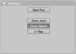
This panel just contains a few toggle buttons. When the Rest Pos toggle is activated (Figure 5), the armature will be displayed in its rest position. This is useful if it becomes necessary to edit the mesh associated with an armature after some posing or animation has been done. Note that the Actions and poses are still there, but they are temporarily disabled while this button is pressed.
Draw Axes and Draw Names toggle buttons allow the local axes of each bone and its name to be displayed in the 3D Viewport.
The X-Ray toggle prevents the armature bones from being hidden by your model when in solid/shaded mode.


