Structure
With meshes, everything is built from three basic structures: vertices, edges and faces.

Example of mesh structure.
Vertices
The most elementary part of a mesh is the vertex (vertices plural) which is a single point or position in 3D space. Vertices are represented in the 3D Viewport in Edit Mode as small dots. The vertices of and object are stored as an array of coordinates.
Tip
Do not mistake the object origin for a vertex. It may look similar, but it is bigger and cannot be selected.

The vertex is labeled as “A”; the object’s origin dot is labeled as “B”.
Edges
An edge always connects two vertices by a straight line. The edges are the “wires” you see when you look at a mesh in wireframe view. They are usually invisible on the rendered image. They are used to construct faces.
Faces
Faces are used to build the actual surface of the object. They are what you see when you render the mesh. If this area does not contain a face, it will simply be transparent or non-existent in the rendered image.
A face is defined as the area between either three (triangles), four (quadrangles) or more (n-gons) vertices, with an edge on every side. The faces are often abbreviated to tris, quads & n-gons.
Triangles are always flat and therefore easy to calculate. On the other hand, quadrangles “deform well” and are therefore preferred for animation and subdivision modeling.
Normals
In geometry, a normal is a direction or line that is perpendicular to something, typically a triangle or surface but can also be relative to a line, a tangent line for a point on a curve, or a tangent plane for a point on a surface.
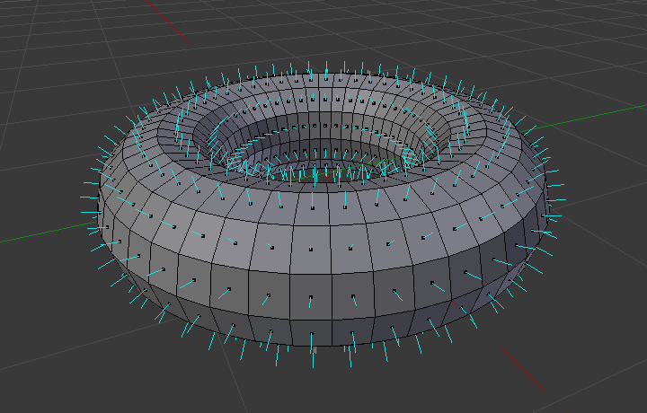
A visualization of the face normals of a torus.
In the figure above, each blue line represents the normal for a face on the torus. The lines are each perpendicular to the face on which they lie. The visualization can be activated, in Edit Mode, in the Mesh Display Viewport Overlays panel.
Properties
Reference
- Panel
Normals panel.
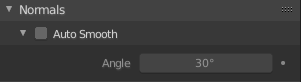
- Auto Smooth
Edges where an angle between the faces is smaller than specified in the Angle field will be smoothed, when shading of these parts of the mesh is set to smooth. This is an easier way to combine smooth and sharp edges.
Example mesh with Auto Smooth enabled.
Advanced Smooth Shading & Sharp Edges
By default in Blender, with basic normal computing behavior, a sharp edge is always defined as an edge being either non-manifold, or having at least one of its faces defined as flat.
Enabling the Auto Smooth setting adds an extra parameter to define a sharp edge, the Angle threshold between two neighbor faces, above which the edge will always be considered as sharp.
Auto Smooth also enables Custom Split Normals handling, which can be either defined (and edited) as a mesh data layer, or generated on the fly by modifiers. In any case, when a mesh gets custom normals, they always supersede the default ones computed by Auto Smooth.
Sharp edges may still be used by the custom normals modifiers to compute their normals, depending on their settings.
Custom Split Normals
Custom Split Normals is a way to tweak/fake shading by pointing normals towards other directions than the default, auto-computed ones. It is mostly used in game development, where it helps counterbalance some issues generated by low-poly objects (the most common examples are low-poly trees, bushes, grass, etc. and the ‘rounded’ corners).
Blender supports custom normals on a ‘smooth fan’ base, defined as a set of neighbor face corners sharing the same vertex and ‘linked’ by smooth edges. This means you can have normals per face corners, per a set of neighbor face corners, or per vertex.
Enabling Custom Split Normals
Reference
- Mode
Edit Mode
- Menu
Enables custom split normals. Also, any of the custom normal editing tools (see below) will, as a convenience, enable custom normals if they are not already enabled.
Note
This has the side effect of enabling Auto Smooth, as that is necessary to use custom normals. Once you have custom normals, the angle threshold of the Auto Smooth behavior is disabled – all non-sharp-tagged edges will be considered as smooth, disregarding the angle between their faces.
Editing Custom Split Normals
Reference
- Mode
Edit Mode
- Menu
- Shortcut
Alt-N
There are a number of tools for editing custom split normals. The custom normal mesh edit tools can affect all normals (the default), or only selected ones. To select a custom normal associated with a particular vertex and face:
Make the element selection mode both Vertex and Face (use Shift-LMB to enable the second one).
Select one or more vertices, then select a face. This can be repeated to select more vertices and a different face and so on. It is easiest to see the effect of these tools if you turn on the Edit Mode Overlays option Display vertex-per-face normals as lines.
See also
Importing Custom Split Normals
Some tools, particularly those used in CAD, tend to generate irregular geometry when tessellating their objects into meshes (very thin and long triangles, etc.). Auto-computed normals on such geometry often gives bad artifacts, so it is important to be able to import and use the normals as generated by the CAD tool itself.
Note
Currently, only the FBX Importer and Alembic Importer are capable of importing custom normals.
Topology
Loops
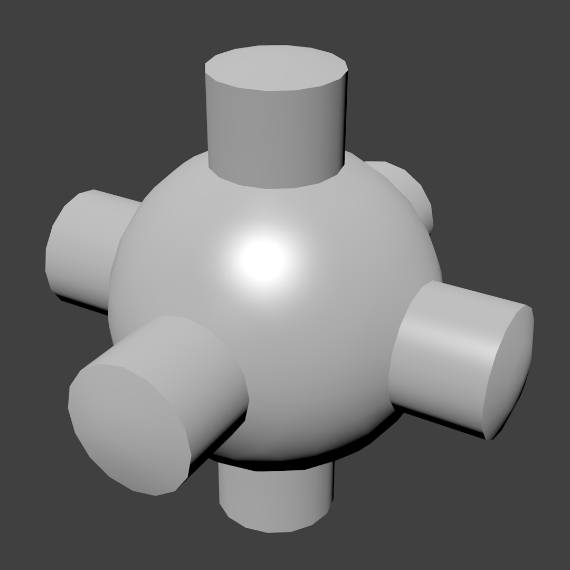
Edge and face loops.
Edge and face loops are sets of faces or edges that form continuous “loops” as shown in Fig. Edge and face loops..
In the image above, loops that do not end in poles are cyclic (1 and 3). They start and end at the same vertex and divide the model into two partitions. Loops can be a quick and powerful tool to work with specific, continuous regions of a mesh and are a prerequisite for organic character animation. For a detailed description of how to work with loops in Blender, see: Edge Loop Selection.
Note
Note that loops (2 and 4) do not go around the whole model. Loops stop at so-called poles because there is no unique way to continue a loop from a pole. Poles are vertices that are connected to either three, five, or more edges. Accordingly, vertices connected to exactly one, two or four edges are not poles.
Edge Loops
Loops (1 and 2) in Fig. Edge and face loops. are edge loops. They connect vertices so that each one on the loop has exactly two neighbors that are not on the loop and placed on both sides of the loop (except the start and end vertex in case of poles).
Edge loops are an important concept especially in organic (subsurface) modeling and character animation. When used correctly, they allow you to build models with relatively few vertices that look very natural when used as subdivision surfaces and deform very well in animation.
Take Fig. Edge and face loops. in organic modeling as an example: the edge loops follow the natural contours and deformation lines of the skin and the underlying muscles and are more dense in areas that deform more when the character moves, for example at the shoulders or knees.
Further details on working with edge loops can be found in Edge Loop Selection.
Face Loops
These are a logical extension of edge loops in that they consist of the faces between two edge loops, as shown in loops (3 and 4) in Fig. Edge and face loops.. Note that for non-circular loops (4) the faces containing the poles are not included in a face loop.
Further details on working with face loops can be found in Face Loop Selection.
Poles
See N-poles & E-poles.
Non-Manifold
See Non-manifold.