Surface
Surface editing has even fewer tools and options than its curve counterpart, but has many common points with it… So this page covers (or tries to cover) all the subjects, from the basics of surface editing to more advanced topics, like retopology.
Transform
Reference
- Mode
Edit Mode
- Menu
A surface can be edited by transforming the locations of the control points.
- Move, Rotate, Scale
Like other elements in Blender, control points can be moved, rotated, or scaled as described in Basic Transformations.
- To Sphere, Shear, Warp, Bend, Push/Pull, Warp, Randomize
These transform tools are described in the Transformations sections.
- Move/Scale Texture Space
Like other objects, surfaces have textures spaces which can be edited.
Mirror
Reference
- Mode
Edit Mode
- Menu
- Shortcut
Ctrl-M
The Mirror tool is also available, behaving exactly as with mesh vertices.
Snap
Reference
- Mode
Edit Mode
- Menu
- Shortcut
Shift-S
Mesh snapping also works with control points, except for within itself (other components of the active spline). Snapping works with 2D surfaces but points will be constrained to the local XY axes.
Spin
Reference
- Mode
Edit Mode
- Menu
This tool is a bit similar to its mesh counterpart but with less control and options (in fact, there is none!).
It only works on selected “surfaces” made of one U row (and not with one V row), so-called “surface curves”, by “extruding” this “cross section” in a square pattern, automatically adjusting the weights of control points to get a perfect circular extrusion (this also implies closing the surface along the V axis), following exactly the same principle as for the NURBS Tube or NURBS Donut primitives.
Add Duplicate
Reference
- Mode
Edit Mode
- Menu
- Shortcut
Shift-D
Similar as with meshes and curves, this tool duplicates the selection. The copy is selected and placed in move mode, so you can move it to another place.
However, with surfaces there are some selections that cannot be duplicated, in which case they will just be placed in move mode… In fact, only selections forming a single valid sub-grid are copiable; let us see this in practice:
You can copy a single control point. From it, you will be able to “extrude” a “surface curve” along the U axis, and then extrude this unique U row along the V axis to create a real new surface.
You can copy a single continuous part of a row (or a whole row, of course). This will give you a new U row, even if you selected (part of) a V row!
You can copy a single whole sub-grid.
Note
Trying to duplicate several valid “sub-grids” (even being single points) at once will not work; you will have to do it one after the other…
Split
Reference
- Mode
Edit Mode
- Menu
- Shortcut
Y
The Split operator splits a selected segment of a surface from the rest of the surface. This segment can then be moved or altered without affecting the other surface. If a single control point is selected the Split operator will create a new singular loose control point; leaving the previously selected control point attached to the rest of the surface.
Separate
Reference
- Mode
Edit Mode
- Menu
- Shortcut
P
Surface objects that are made of multiple distinct parts can be separated into their own objects by selecting the desired segments and using Separate. Note, if there is only one surface in a surface object, Separate will create a new surface object with no control points.
Toggle Cyclic
Reference
- Mode
Edit Mode
- Menu
- Shortcut
Alt-C
As in curves, surfaces can be closed (cyclic) or open. However, as surfaces are 2D, you can control this property independently along the U and V axes.
To toggle the cyclic property of a surface along one axis, use Toggle Cyclic and choose either Cyclic U or Cyclic V from the pop-up menu. The corresponding surface’s outer edges will join together to form a “closed” surface.
Note
Inner and Outer
Surfaces have an “inner” and “outer” face, the first being black whereas the latter is correctly shaded. When you close a surface in one or two directions, you might get an entirely black object! In this case, just Switch Direction of the surface.
Show/Hide
Reference
- Mode
Edit Mode
- Menu
- Shortcut
Alt-H, H, Shift-H
When in Edit Mode, you can hide and reveal elements from the display. You can only show or hide control points, as segments are always shown, unless all control points of the connected surface are hidden, in which case the surface is fully hidden.
See also
See Show/Hide in Object Mode.
Delete
Reference
- Mode
Edit Mode
- Menu
- Shortcut
X, Delete
The selection must abide by the following rules:
Whole rows, and only whole rows must be selected.
Only rows along the same axis must be selected (i.e. you cannot delete both U and V rows at the same time).
Also remember that NURBS order cannot be higher than its number of control points in a given axis, so it might decrease when you delete some control points… Of course, when only one row remains, the surface becomes a “surface curve”; when only one point remains, there is no more visible surface; and when all points are deleted, the surface itself is deleted.
- Vertices
This will delete the selected rows, without breaking the surface (i.e. the adjacent rows will be directly linked, joined, once the intermediary ones are deleted). Remember that NURBS order cannot be higher than its number of control points, so it might decrease when you delete some control point. Of course, when only one point remains, there is no more visible curve, and when all points are deleted, the curve itself is deleted.
- Segment
Deletes the segment that connects the selected control points and disconnects them.
- Dissolve Vertices Ctrl-X
This feature only works for Curves.
Example
In the image below (left), a row of control points has been selected by initially selecting the one control point and using Select Control Point Row to select the remaining control points. Then, using Delete Vertices, the selected row of control points is erased, resulting in the image below (right).
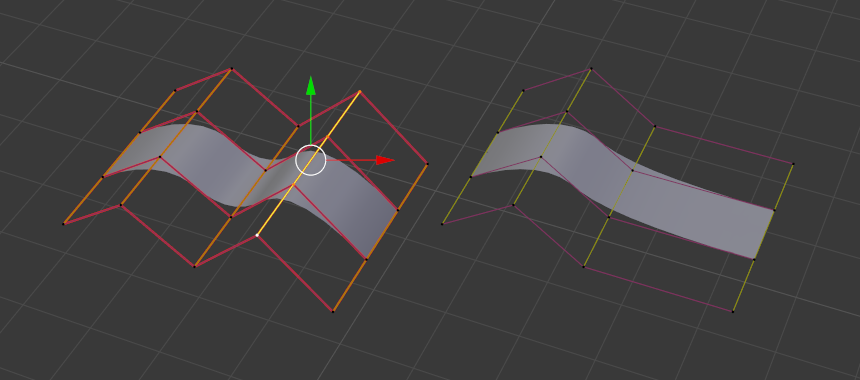
Before and after.