Math Node
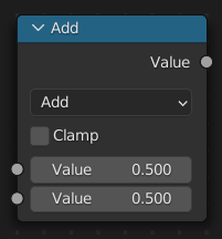
The Math Node performs math operations.
Inputs
The inputs of the node are dynamic. Some inputs are only available in certain operations. For instance, the Addend input is only available in the Multiply Add operator.
- Value
Input Value. Trigonometric functions read this value as radians.
- Addend
Input Addend.
- Base
Input Base.
- Exponent
Input Exponent.
- Epsilon
Input Epsilon.
- Distance
Input Distance.
- Min
Input Minimum.
- Max
Input Maximum.
- Increment
Input Increment.
- Scale
Input Scale.
- Degrees
Input Degrees.
- Radians
Input Radians.
Properties
- Operation
The mathematical operator to be applied to the input values:
- Functions
- Add
The sum of the two values.
- Subtract
The difference between the two values.
- Multiply
The product of the two values.
- Divide
The division of the first value by the second value.
- Multiply Add
The sum of the product of the two values with Addend.
- Power
The Base raised to the power of Exponent.
- Logarithm
The log of the value with a Base as its base.
- Square Root
The square root of the value.
- Inverse Square Root
One divided by the square root of the value.
- Absolute
The input value is read without regard to its sign. This turns negative values into positive values.
- Exponent
Raises Euler’s number to the power of the value.
- Comparison
- Minimum
Outputs the smallest of the input values.
- Maximum
Outputs the largest of two input values.
- Less Than
Outputs 1.0 if the first value is smaller than the second value. Otherwise the output is 0.0.
- Greater Than
Outputs 1.0 if the first value is larger than the second value. Otherwise the output is 0.0.
- Sign
Extracts the sign of the input value. All positive numbers will output 1.0. All negative numbers will output -1.0. And 0.0 will output 0.0.
- Compare
Outputs 1.0 if the difference between the two input values is less than or equal to Epsilon.
- Smooth Minimum
- Smooth Maximum
- Rounding
- Round
Rounds the input value to the nearest integer.
- Floor
Rounds the input value down to the nearest integer.
- Ceil
Rounds the input value up to the nearest integer.
- Truncate
Outputs the integer part of the value.
- Fraction
- Modulo
Outputs the remainder once the first value is divided by the second value.
- Wrap
Outputs a value between Min and Max based on the absolute difference between the input value and the nearest integer multiple of Max less than the value.
- Snap
Rounds the input value down to the nearest integer multiple of Increment.
- Ping-pong
The output value is moved between 0.0 and the Scale based on the input value.
- Trigonometric
- Sine
The Sine of the input value.
- Cosine
The Cosine of the input value.
- Tangent
The Tangent of the input value.
- Arcsine
The Arcsine of the input value.
- Arccosine
The Arccosine of the input value.
- Arctangent
The Arctangent of the input value.
- Arctan2
Outputs the Inverse Tangent of the first value divided by the second value measured in radians.
- Hyperbolic Sine
The Hyperbolic Sine of the input value.
- Hyperbolic Cosine
The Hyperbolic Cosine of the input value.
- Hyperbolic Tangent
The Hyperbolic Tangent of the input value.
- Conversion
- To Radians
Converts the input from degrees to radians.
- To Degrees
Converts the input from radians to degrees.
- Clamp
Limits the output to the range (0.0 to 1.0). See Clamp.
Outputs
- Value
Numerical value output.
Examples
Manual Z-Mask
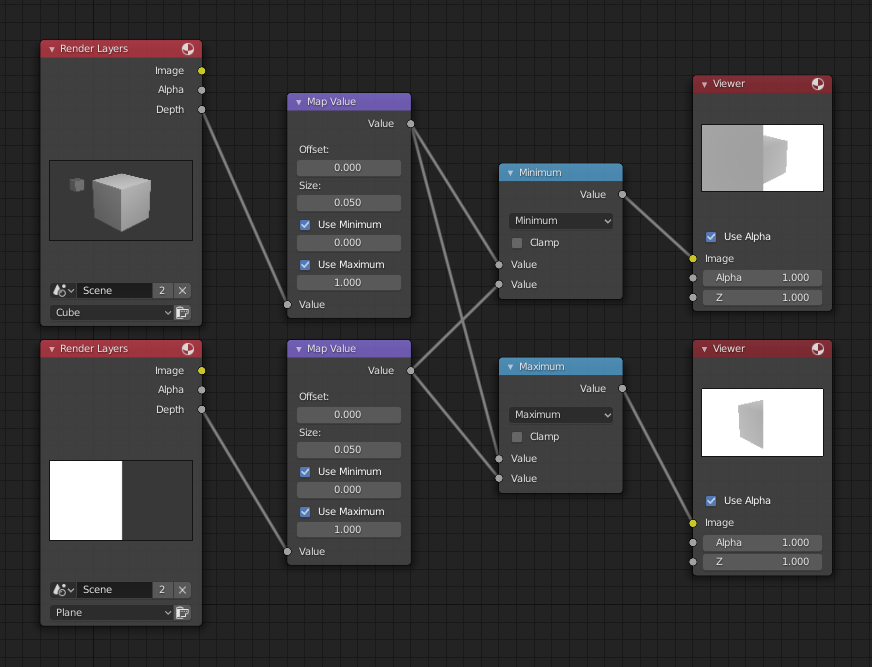
Minimum and maximum function example.
This example has one scene input by the top Render Layers node, which has a cube that is about 10 units from the camera. The bottom Render Layers node inputs a scene with a plane that covers the left half of the view and is 7 units from the camera. Both are fed through their respective Map Value nodes to divide the Z-buffer by 20 (multiply by 0.05, as shown in the Size field) and clamped to be a min/max of 0.0/1.0 respectively.
For the minimum function, the node selects those Z values where the corresponding pixel is closer to the camera; so it chooses the Z values for the plane and part of the cube. The background has an infinite Z value, so it is clamped to 1.0 (shown as white). In the maximum example, the Z values of the cube are greater than the plane, so they are chosen for the left side, but the plane Render Layers Z are infinite (mapped to 1.0) for the right side, so they are chosen.
Using Sine Function to Pulsate
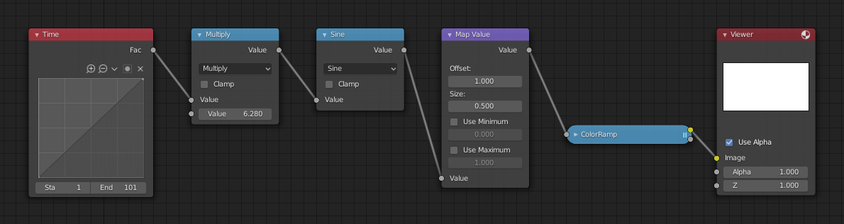
Using sine function example.
This example has a Time node putting out a linear sequence from 0 to 1 over the course of 101 frames. At frame 25, the output value is 0.25. That value is multiplied by 2 × pi (6.28) and converted to 1.0 by the Sine function, since \(sin(2 × pi/ 4) = sin(pi/ 2) = +1.0\).
Since the sine function can put out values between (-1.0 to 1.0), the Map Value node scales that to 0.0 to 1.0 by taking the input (-1 to 1), adding 1 (making 0 to 2), and multiplying the result by one-half (thus scaling the output between 0 to 1). The default Color Ramp converts those values to a gray-scale. Thus, medium gray corresponds to a 0.0 output by the sine, black to -1.0, and white to 1.0. As you can see, \(sin(pi/ 2) = 1.0\). Like having your own visual color calculator! Animating this node setup provides a smooth cyclic sequence through the range of grays.
Use this function to vary, for example, the alpha channel of an image to produce a fading in/out effect. Alter the Z channel to move a scene in/out of focus. Alter a color channel value to make a color “pulse”.
Brightening (Scaling) a Channel
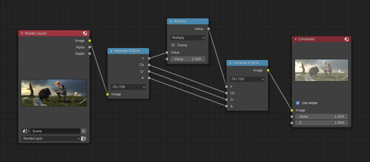
Scaling a channel example.
This example has a Math (Multiply) node increasing the luminance channel (Y) of the image to make it brighter. Note that you should use a Map Value node with min() and max() enabled to clamp the output to valid values. With this approach, you could use a logarithmic function to make a high dynamic range image. For this particular example, there is also a Bright/Contrast node that might give simpler control over brightness.
Restrict Color Selection (Posterization)
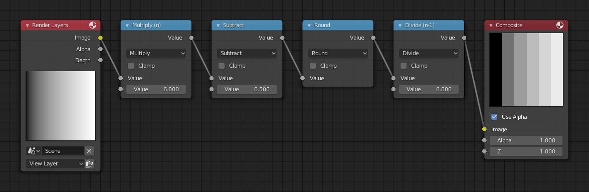
Posterization example.
In this example, we restrict the color values to be one of the six values: 0, 0.2, 0.4, 0.6, 0.8, 1.
To split up a continuous range of values between 0 and 1 to certain set of values, the following function is used: \(round(x × n - 0.5) / (n - 1)\), where “n” is the number of possible output values, and “x” is the input pixel color. Read more about this function.
To implement this function in Blender, consider the node setup above. We string the Math nodes into a function that takes each color (values from 0 to 1), multiplies it up by six, the desired number of divisions (values become from 0 to 6), offsets it by 0.5 (-0.5 to 5.5), rounds the value to the nearest whole number (produces 0, 1, 2, 3, 4, 5), and then divides the image pixel color by five (0.0, 0.2, 0.4, 0.6, 0.8, 1.0).
In the case of a color image, you need to split it into separate RGB channels using Separate/Combine RGBA nodes and perform this operation on each channel independently.