Linea di Comando
This section deals with the PDT Command Line, a system whereby PDT Operations & Tools can be entered as keyed text rather than using the buttons and input boxes.
The Menu For Command Line
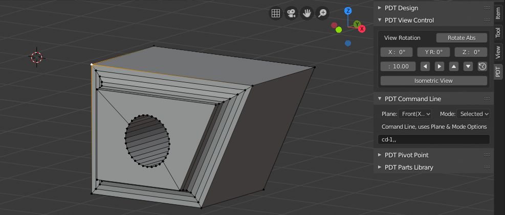
Here the Cursor has been set with the command cd-1.5,, placing the cursor negative 1.5 in X from the selected vertex.
PDT has a Command Input, which activates when you press Return. this takes two letters, followed by numbers separated by commas “,”. Valid Primary letters are, can be capitals, or lower case:
C = Cursor commands.
D = Duplicate commands
E = Extrude Geometry commands
F = Fillet Commands
G = Grab, or move commands.
N = New Vertex commands.
P = Pivot commands.
S = Split Edges.
V = Extrude Vertices only, not their edges, or faces.
Valid Secondary letters are, can be capitals, or lower case:
A = Absolute, or World coordinates and requires 3 numbers separated by 2 commas, zeros may be omitted, so *cd2,,1* is valid.
D = Delta, or incremental coordinates and has the same requirements as A.
I = Direction and requires a distance and an angle, separated by a comma, from View Horizontal, so ei2,135.6 means extrude geometry 2 units at 135.6 degrees from positive view X axis. Valid Angle range is +-180.
P = Use a percentage value to, for example, split an edge, so sp30 means split edge at 30% of the way along it.
Principles:
To operate the Command Line, first you must RMB-click in the input box, then type,
or amend the command there, then press Return to activate the command.
I will explore ways of capturing commands directly from the keyboard,
maybe by using a “trigger” input first.
For example, key ALT+P first then the command, with a «watcher» routine to send subsequent inputs to the command line, I do not know if this is possible yet.
Operations (First Letter):
Cursor Commands will use the Plane setting for commands related to distance
and angle and also will use the Mode setting of either Current, or Selected.
This setting related to whether incremental cursor changes are relative
to the current position of the cursor, or the Active vertex.
A command of cp30 will place the cursor 30% of the way between two selected vertices for example. Error messages will tell you if your command is not a valid option, or if you do not have sufficient vertices/objects selected, or if you do not have sufficient values in your command. For example, d options (delta) require three values separated by two commas, p options require only one value. Mathematical Expressions are not evaluated in this way. In other cases, all missing values, or invalid values are converted to 0.
Pivot Point Commands, like cursor commands, will use the Plane setting for commands
related to distance and angle and also will use the Mode setting of either Current, or Selected.
This setting related to whether incremental cursor changes are relative
to the current position of the cursor, or the Active vertex.
A command of pi1,135 will place the Pivot Point 1m at 135 degrees from the Active vertex.
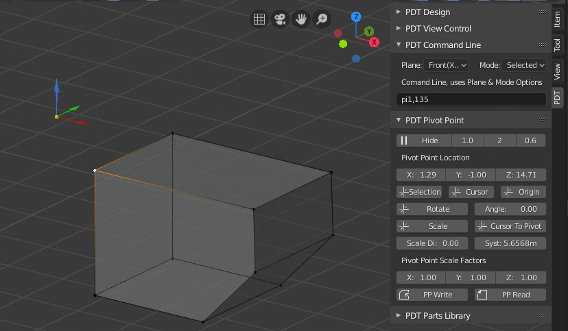
Grab commands will move selected objects, or vertices by the values input,
so if Plane is set to View and the command is gi1.5,38.75
the selection will be moved a distance of 1.5 at 38.75 degrees to the view’s
horizontal axis and in line with the views orientation to your screen.
New Vertex commands will place a new vertex as described by the values, so na1.5,,1.2 will place a new vertex at Absolute (Global if you prefer) X = 1.5, Y = 0 , Z = 1.2.
Extrude Vertices commands will only extrude the selected vertices, not their associated edges, or faces. A command of vd,3, will extrude the selected vertices 0 in X, 3 in Y and 0 in Z.
Duplicate Geometry commands will duplicate the selected geometry. A command of dd,5, will duplicate the selected geometry 0 in X, 5 in Y and 0 in Z.
Extrude Geometry commands will extrude the selected geometry, edges and faces included. A command of ed1,3,2 will extrude the selected geometry 1 in X, 3 in Y and 2 in Z.
Split commands can be operated in a number of geometry situations, so for example, if you want to split a Face like this:
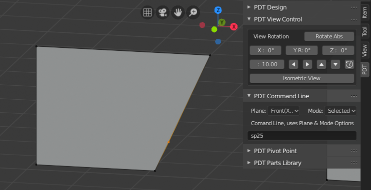
Image showing the new vertex inserted 25% of the way along the edge using the command sp25.
In this next scenario, we have split an extruded Face, producing an Ngon:
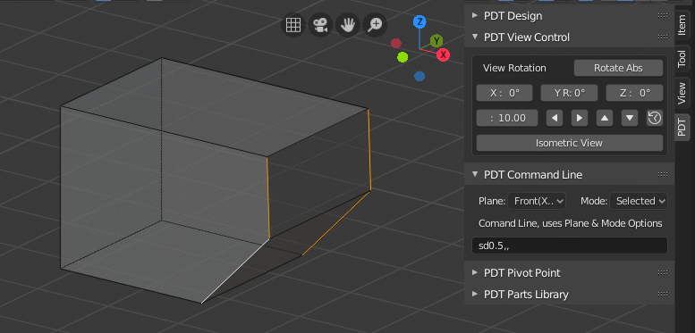
Command was sd0.2,, a new edge has been created and topological integrity preserved.
In all cases the edges are split in two and then new vertex/vertices from these operations are then moved according to the command parameters. If you select such a combination of edges as to make a face, an error message is returned and the operation cancelled as this will, in all likelihood, result in bad topology.
Fillet commands will Fillet, or Bevel a corner, for single vertex corners, as in an edge loops, use the _v_ second letter, for edges, use _e_ second letter. this command requires 3 values; radius, number of segments and profile. Profile should be in range 0 to 1, 0.005 is a _convex_ fillet, 0.5 is a _concave_ fillet. So a command of fv1.5,6,0.5 will fillet vertices to radius 1.5, 6 segments, concave fillet.
Note!
Obviously unworkable commands like da1,3,4 (duplicate geometry to an absolute location, resulting in all duplicate vertices having the same location) will quite reasonably result in an error message.
Maths Mode:
Maths function («M» primary letter) enable maths calculations to be input into other input boxes in PDT Design, so for example if you want to set the X input to 1.2 * Sine(54), that can be done. Additional Second Letters are introduced for this function, namely:
X - send output to X Coord.
Y - send output to Y Coord.
Z - send output to Z Coord.
D - send output to Distance.
A - send output to Angle.
P - send output to Percent.
O - Send Output to Maths Out Field.
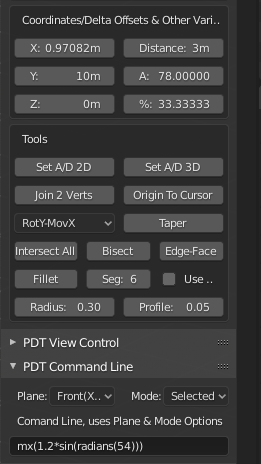
So, in the option quoted above, a command of mx(1.2*sin(radians(54))) results in the X coord being set to 0.97082:
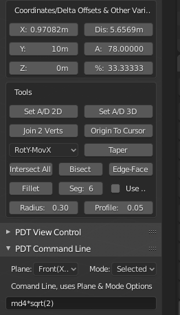
Alternatively a command of md4*sqrt(2) results in the Distance input being set to 5.65685:
From Version 1.1.8, Maths Function now can output to the Maths Output field:
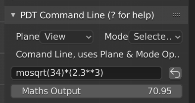
Here the command mosqrt(34)*(2.3**3) was used, meaning; Maths, Output, Square Root of 34 times 2.3 cubed. This value can be copied by floating your mouse over the field and keying CTRL+C, it can then be pasted anywhere.
There is also a Re-Run Last Command button to submit the last command line input, as shown in the image above.
Command Line Additions for v1.2.0 & above.
With the introduction of v1.2.0, more commands have been introduced to the Command Line module, they are:
ad2 Does what Set A/D 2D button does, ie. measure distance & angle from 2 points.
ad3 Does what Set A/D 3D button does, ie. measure distance & angle from 3 points.
j2V Does what Join 2 Verts button does, i.e. join 2 vertices into an edge.
bis Does what Bisect button does, i.e. bisect two intersecting edges.
etf Does what Edge To Face button does, i.e. extrude edge to intersecting face.
intall Does what Intersect All button does, i.e. break a set of edges where they intersect.
tap Does what Taper button does, i.e. taper geometry at a user defined angle and axis set.
otc Does what Origin To Cursor button does, i.e. set the object origin to the cursor location.
Then there are the three special cases of nml, cen & int. These should be preceded by the Operation letter, see Valid First Letters above, so putting the cursor at the intersection of two edges would be done with the command cint, creating a new vertex at the normal intersection would be done with the command vnml.
Clicking on any of the buttons in PDT Design Operations, or PDT Design Tools
will write the equivalent command line expression into the command line input.
So for example, filleting edges at 0.5 radius, 6 segments and 0.05 profile,
as set in the inputs & using the Fillet button will write fe0.5,5,0.05 into the command line input.
Entering a blank expression into the command line will result in No Action, i.e. it will be ignored.