Геометрія – Geometry
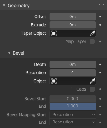
Панель «Геометрія» – Geometry.
- Зсув – Offset
Переміщує видавлення паралельно до нормалей кривої.
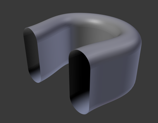
Коло Безьє: Offset – -1, Extrusion – 0.5, Bevel: Depth – 0.25, Bevel: Resolution – 10.
- Видавлення – Extrude
Буде видавлюватися крива уздовж обох додатного та від’ємного напрямків локальної осі Z. Перетворює одно-вимірну криву у дво-вимірну криву, додаючи їй висоту. З масштабом – це сума обох напрямків, перпендикулярно до нормалей кривої.
Коло Безьє: Extrude – 0.0 (Edit Mode).
Коло Безьє: Extrude – 0.5 (Object Mode).
- Об’єкт Звуження – Taper Object
Tapering a curve causes it to get thinner towards one end. You can also alter the proportions of the Taper throughout the tapered object by moving/scaling/rotating the control points of the Taper Object. The taper curve is evaluated along the local X axis, using the local Y axis for width control. In order for this to work the Taper Object can only be another open curve.
The details are:
Звуження застосовується незалежно до всіх кривих видавленого об’єкта.
Обчислюється лише перша крива для Taper Object, навіть якщо ви маєте у ньому кілька окремих сегментів.
Масштабування починається у першій керувальній точці зліва та йде уздовж кривої до останньої керувальної точки справа.
Також можливе від’ємне масштабування (від’ємна локальна Y на кривій звуження). Однак, можуть з’являтися артефакти рендерингу.
You may need to increase the curve resolution to see more detail of the taper.
The Taper Object is distributed by control points. Therefor unevenly spaced control points may likelier to stretch the shape of the taper. Subdividing segments causes those points to use a larger fraction of the overall taper shape.
Для закритих кривих крива звуження у Taper Object діє уздовж усієї кривої (периметр об’єкта), а не тільки по довжині об’єкта, та змінює глибину видавлення. У цих випадках ви бажаєте мати відносну висоту Taper Object Крива звуження на обох кінцях є однаковою, а тому точка зациклення (місце, де кінцева точка кривої з’єднується з її початком) є плавним переходом.
Підказка
Editing the handles and control points of the Taper Object will instantly change the shape of the original object.
- Розкладка Звуження – Map Taper
Для кривих, що використовують Об’єкт Звуження та за допомогою модифікацій Start/End Bevel Factor опція Map Taper буде застосовувати звуження до скошеної частини кривої (не до всієї кривої).
Скіс – Bevel
Round
- Глибина – Depth
Змінює розмір скосу.
A curve with different Bevel depths applied (Depth of 0.05).
A curve with different Bevel depths applied (Depth of 0.25).
- Роздільність – Resolution
Змінює плавність скосу.
A curve with different resolutions applied (Resolution of 1).
A curve with different resolutions applied (Resolution of 12).
- Заповнити Торці – Fill Caps
Запечатує кінці скошеної кривої.
Об’єкт – Object
- Об’єкт – Object
Here you can specify a curve object (opened or closed) which will be extruded along the curve. If your object’s shape is 3D, it will be projected to its local XY plane before the extrusion. You can check how the projected Object looks like by switching its shape to 2D.
Важливо
Make sure the shape you want to extrude is in the Object’s local XY plane. If it is in the local XZ or YZ plane, it will be reduced to a line when it is projected to the local XY plane. Because of this, the extruded shape will be a flat plane.
A curve with a Bézier curve as the Bevel Object.
A curve with a Bézier circle as the Bevel Object.
Profile
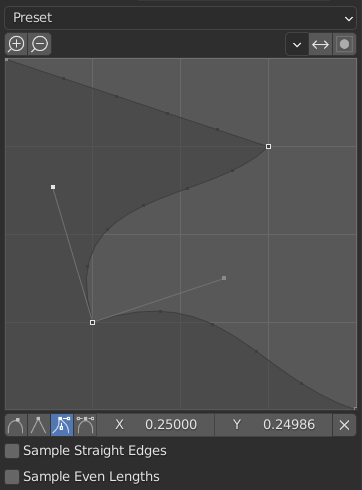
The custom profile widget.
This widget allows the creation of a user-defined profile with more complexity than with the single profile parameter. The modal tool allows toggling the custom profile, but the shape of the profile is only editable in the options panel after the operation is confirmed.
The profile starts at the bottom right of the widget and ends at the top left, as if it were between two edges intersecting at a right angle. Control points are created in the widget and then the path is sampled with the number of segments from the Bevel modifier.
Примітка
The Profile slider stays active when miters are enabled because it still controls the shape of the miter profiles.
- Presets
The Support Loops and Steps presets are built dynamically depending on the number of segments in the bevel. If the number of segments is changed, the preset will have to be re-applied.
- Sampling
Samples will first be added to each control point, then if there are enough samples, they will be divided evenly between the edges. The Sample Straight Edges option toggles whether the samples are added to edges with sharp control points on either side. If there aren’t enough samples to give each edge the same number of samples, they will just be added to the most curved edges. So it is recommended to use at least as many segments as there are control points.
Start & End Mapping
- Factor Start, End
These options determine where to start/end the geometry of the curve. This allows to make a curve which is not fully covered with geometry.
Increasing the start value to 0.5 will start the geometry at 50% of the distance from the start of the curve (in effect shortening the curve). Decreasing the end value by 0.25 will start the geometry at 25% of the distance from the end of the curve (again, shortening the curve).
A curve with no Factor Start, End.
A curve with a 0.6 End factor.
- Mapping Start, End
Allows to control the relation between the Factor Start, End (number between 0 and 1) and the rendered start and end point of the spline’s geometry.
- Роздільність – Resolution
Maps the start and end factor to the number of subdivisions of a spline (U resolution).
- Сегменти – Segments
Maps the start and end factor to the length of its segments. Mapping to segments treats the subdivisions in each segment of a curve as if they would have all the same length.
- Сплайн – Spline
Maps the start and end factor to the length of a spline.
Приклади – Examples
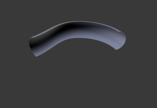
Відкрита 2D крива
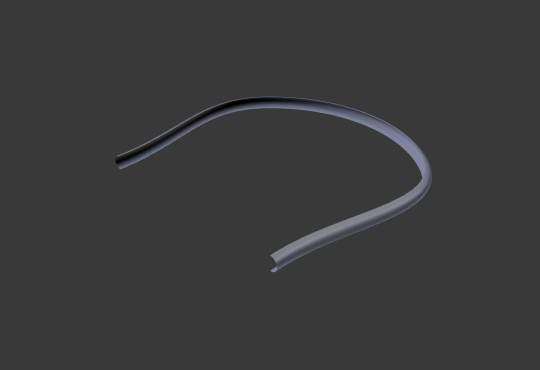
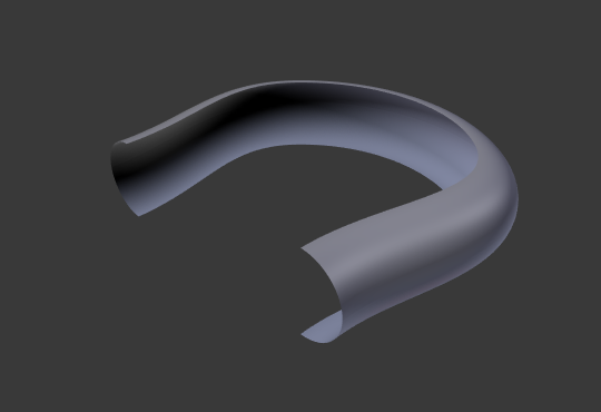
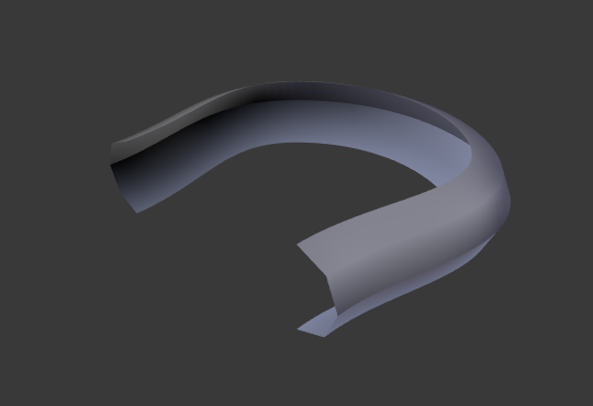
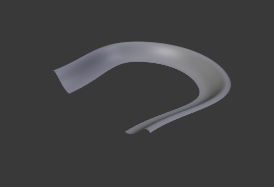
Видавлення буде створювати «стіну» або «стрічку», що відповідає формі кривої. Якщо використовується Bevel Depth, то така стіна стає своєрідною ковзанкою або жолобом. Якщо нормалі вказують у невірному напрямку, то ви можете перемкнути їх напрямок, як показано тут – here.
Відкрита 2D Крива за допомогою Alt-C, заповнення установлено у нуль, нульовий зсув, видавлення як 0.5, Bevel Depth як 0.25, Bevel Resolution як 10.
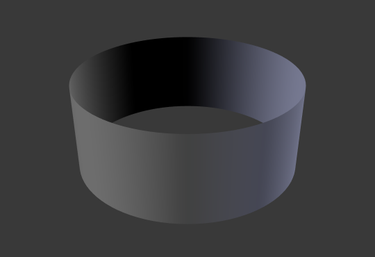
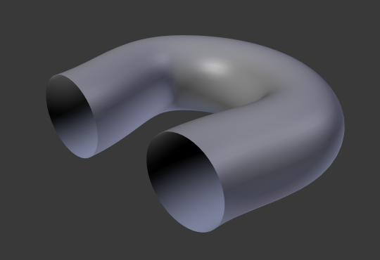
Закрита 2D крива
Це можливо найбільш корисна ситуація, оскільки вона швидко створює об’єм з (стандартно) двома плоскими та паралельними поверхнями, що заповнюють дві сторони видавленої «стіни». Ви можете вилучити одну чи обидві ці грані, вибравши потрібний режим заповнення: Both, Front, Back чи None.
Додаткова глибина скошування буде завжди створювати тут 90-градусні скоси.
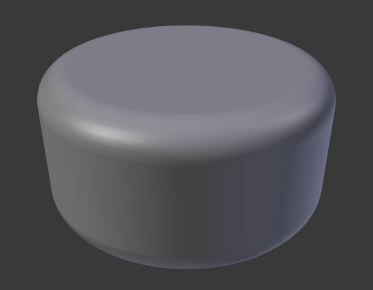
Закрита 2D Крива, Extrude 0.5, Bevel Depth 0.25, Bevel Resolution 10, Fill: Both.
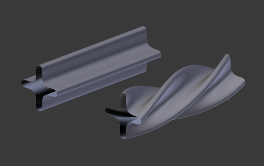
3D крива
Тут той факт, що немає значення – чи відкрита чи закрита крива – ви ніколи не отримаєте об’єм з видавленої 3D кривої, тільки стіну або стрічку, як з відкритими 2D кривими.
Однак, для 3D кривих є одна особливість: відхил Tilt керувальних точок (дивіться вище). Це буде робити стрічку закрученою навколо кривої для створення смужки Мебіуса, наприклад.
Звуження – Taper
Давайте, звузимо простий видавлений об’єкт кривої-кола за допомогою іншої кривої звуження. Додайте криву, а далі вийдіть з режиму редагування Edit Mode. Додайте іншу криву (закриту, наприклад, коло); назвіть її «BevelCurve», та уведіть її ім’я у полі Bevel Object для першої кривої (вкладка дані об’єкта для Curve). Тепер ми маємо трубу. Знаходячись у режимі об’єкта Object Mode, додайте третю криву та назвіть її «TaperCurve». Наладнайте ліву керувальну точку, піднявши її близько на 5 одиниць.
Тепер поверніться на вкладку для оригінальної, першої кривої та відредагуйте її поле Taper Object на панелі Geometry для посилання її на нову криву звуження, яку ми назвали «TaperCurve». Коли ви натиснете Enter, нова крива звуження застосується негайно ж, результат чого показано на Ілюстрації Крива-коло задана як Bevel Object..
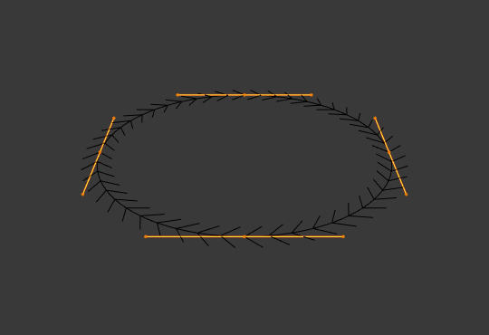
|
Крива-коло задана як Bevel Object.¶ |
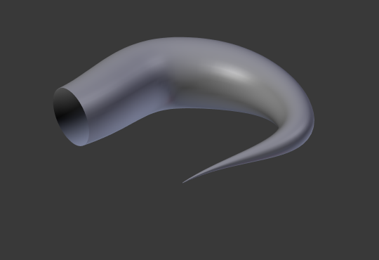
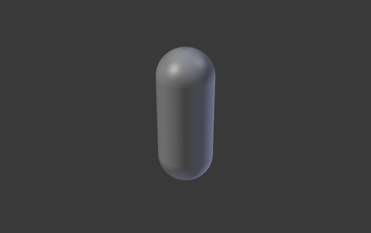
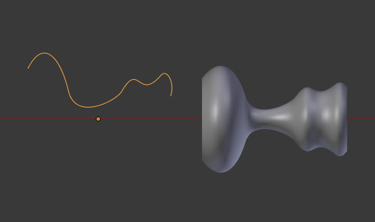
Звуження видавленої кривої.¶ |
Ви можете бачити криву звуження, застосовану до видавленого об’єкта. Зауважте, як об’єм труби звужується до нуля, оскільки крива звуження йде зліва направо. Якщо крива звуження вийде нижче локальної осі ігрек, то внутрішня частина труби вийде назовні, що може призвести до артефактів рендерингу. Звичайно, як для митця, це може бути тим, що ви шукаєте!
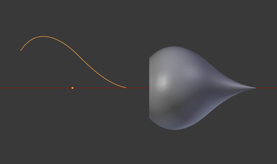
Приклад звуження 1.
На Ілюстрації Приклад звуження 1. ви можете ясно бачити ефект, який крива звуження зліва має на оригінальний об’єкт кривої справа. Тут крива звуження зліва є ближче до початку оригінального об’єкта, що дає менший об’єкт кривої справа.
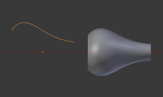
Приклад звуження 2.
На Ілюстрації Приклад звуження 2. керувальна точка кривої звуження зліва пересунута далі від початку об’єкта і це дає ширший результат на об’єкті кривої справа.
Приклад звуження 3.
На Ілюстрації Приклад звуження 3. ми бачимо використання більш нерегулярної кривої звуження, застосованої до оригінальної кривої-кола.
Приклад скошеного видавлення з Tilt.