Đinh Vít (Screw)
Tham Chiếu (Reference)
- Chế Độ (Mode):
Chế Độ Biên Soạn (Edit Mode)
- Trình Đơn (Menu):
Công cụ "Đinh Vít" kết hợp một "Vòng Xoáy" lặp đi lặp lại với một phép tịnh tiến, để tạo ra một đối tượng giống như đinh vít hoặc hình xoắn ốc. Sử dụng công cụ này để tạo các đinh vít, lò xo hoặc cấu trúc hình vỏ sò (các mặt cắt vỏ sò, đầu đinh vít gỗ, và các mặt cắt đặc biệt, v.v.).
Sự khác biệt chính giữa công cụ Đinh Vít và Bộ Điều Chỉnh Đinh Vít (Screw Modifier) là công cụ Đinh Vít có thể tự động tính toán sự tiến triển của góc độ bằng cách sử dụng góc của mặt cắt cơ bản. Nó cũng có thể điều chỉnh vectơ góc Trục mà không cần sử dụng đến bộ điều chỉnh thứ hai nào cả (ví dụ, sử dụng Bộ Điều Chỉnh Đinh Vít với một Bộ Điều Chỉnh Bo Tròn, Bộ Điều Chỉnh Đường Cong, v.v.), dẫn đến cách tiếp cận mạch lạc hơn nhiều đối với việc phân phối và sử dụng điểm đỉnh.
This tool works using open or closed profiles, as well as profiles closed with faces. You can use profiles like an open-edge part that is a part of a complete piece, as well as a closed circle or a half-cut sphere, which will also close the profile end.
Bạn có thể xem một số ví dụ về các khung lưới được tạo bằng công cụ "Đinh Vít" trong hình minh họa Mũi Đinh Vít Gỗ được tạo bằng công cụ Đinh Vít. và hình minh họa Lò Xo được tạo bằng công cụ Đinh Vít..
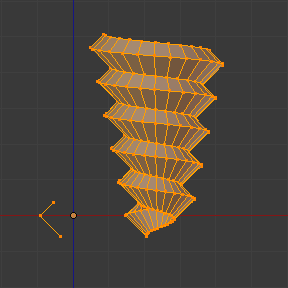
Mũi Đinh Vít Gỗ được tạo bằng công cụ Đinh Vít. |
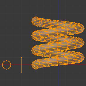
Lò Xo được tạo bằng công cụ Đinh Vít. |
Cách Sử Dụng (Usage)
Công cụ này chỉ hoạt động với các khung lưới mà thôi. Trong "Chế Độ Biên Soạn", bạn có thể tìm thấy thao tác công cụ "Đinh Vít" bằng cách điều hướng đến trong thanh tiêu đề của Cổng Nhìn 3D. Để sử dụng công cụ này, bạn cần phải tạo ít nhất một mặt cắt mở hoặc một đường thẳng để sử dụng làm vectơ cho chiều cao, và một vectơ góc để chỉ định một chiều hướng.
Công cụ "Đinh Vít" sử dụng hai điểm đã cho bởi đường thẳng mở, tạo vectơ ban đầu để tính chiều cao và góc cơ bản của vectơ tịnh tiến. Góc này sẽ được cho thêm vào "Vòng Xoáy" sau mỗi vòng quay hoàn chỉnh (xem ví dụ dưới đây). Nếu vectơ được tạo chỉ với hai điểm đỉnh tại vị trí XYZ "giống nhau" (tức cái sẽ không cung cấp cho Blender giá trị vectơ về chiều cao) thì chức năng này sẽ tạo ra một "Vòng Xoáy" bình thường.
Sau khi đã có ít nhất một đường véctơ thì bạn có thể cho thêm các mặt cắt đóng kín hỗ trợ khác đi theo vectơ này trong quá trình đẩy trồi (xem phần Limitations (Những Giới Hạn)). Chiều hướng đẩy trồi được tính toán bởi hai yếu tố quyết định, điểm quan sát trong Không Gian Toàn Cầu và vị trí của con trỏ trong Cổng Nhìn 3D, bằng cách sử dụng tọa độ Toàn Cầu. Mặt cắt và véctơ đều phải được chọn đầy đủ trong "Chế Độ Biên Soạn" trước khi bạn nhấp vào nút "Đinh Vít" (xem phần Limitations (Những Giới Hạn)). Khi bạn đã có véctơ cho mặt cắt mở và các mặt cắt đóng kín khác lựa chọn rồi thì hãy nhấp vào nút "Đinh Vít".
Những Giới Hạn (Limitations)
Có một số điều kiện nghiêm ngặt về việc lựa chọn mặt cắt khi bạn muốn sử dụng công cụ này. Bạn phải có ít nhất có một đường thẳng mở hoặc mặt cắt mở, cung cấp cho Blender Véctơ khởi đầu để sử dụng cho quá trình đẩy trồi, vectơ góc và chiều cao (ví dụ, một cạnh đơn giản, một nửa hình tròn, v.v.). Bạn chỉ cần đảm bảo rằng ít nhất một đường thẳng tham chiếu có hai đầu "thả lỏng". Nếu có hai đường thẳng mở thì Blender sẽ không xác định nổi cái nào trong số chúng là vectơ cả và do đó sẽ hiển thị thông báo lỗi, "Bạn cần phải lựa chọn một trình tự các điểm đỉnh kết nối nữa". Bạn cần chọn toàn bộ các điểm đỉnh mặt cắt tham gia vào hoạt động của công cụ "Đinh Vít"; nếu chúng không được chọn đúng đắn thì Blender sẽ hiển thị cho bạn thông báo lỗi tương tự như trên.
Lưu ý rằng đường thẳng mở sẽ luôn luôn được đẩy trồi, vì vậy nếu bạn chỉ sử dụng nó để "điều hướng" cái đinh vít thì bạn sẽ phải xóa nó đi sau khi công cụ đã hoàn thành (sử dụng lựa chọn liên kết, Ctrl-L, để lựa chọn toàn bộ phần đẩy trồi của đường thẳng mở).
Nếu bất kỳ vấn đề nào xảy ra trong việc lựa chọn hoặc trong các mặt cắt thì công cụ sẽ cảnh báo bạn với thông báo lỗi: ``"Bạn phải chọn một chuỗi các điểm đỉnh được kết nối nữa" như thấy trong hình minh họa Thông báo lỗi của Đinh Vít trên thanh trạng thái. và hình minh họa Thông báo lỗi khi nhấp vào công cụ Đinh Vít với lựa chọn không chính xác hoặc không hợp lệ., cả trong Thanh Trạng Thái (Status Bar) và ở nơi bạn nhấp chuột khởi đầu thực hiện thao tác (khi bạn nhấp vào Nút Đinh Vít).

Thông báo lỗi của Đinh Vít trên thanh trạng thái.

Thông báo lỗi khi nhấp vào công cụ Đinh Vít với lựa chọn không chính xác hoặc không hợp lệ.
You may have as many profiles as you like (like circles, squares, and so on) -- Note that, not all vertices in a profile need to be in the same plane, even if this is the most common case. You may also have other, more complex, selected closed islands, but they have to be closed profiles because Blender will seek for only one open profile for the translation, height and angular vector. Some closed meshes that overlap themselves may not screw correctly (for example: Half UV Sphere works fine, but more than half could cause the Screw tool to have wrong behavior or errors), and profiles that are closed with faces (like a cone or half sphere) will be closed automatically at their ends, like if you were extruding a region.
Mẹo
Phương Pháp Đơn Giản để không dẫn đến Lỗi
Chỉ nên có một Mặt Cắt mở, toàn bộ các mặt cắt khác có thể được đóng kín lại, tránh các khối thể tích và những mặt cắt đóng kín bằng các bề mặt...
Các Tùy Chọn (Options)
Công cụ này là một công cụ tương tác và modal, và chỉ hoạt động trong "Chế Độ Biên Soạn" mà thôi. Khi bạn chọn công cụ "Đinh Vít" thì Blender sẽ bước vào chế độ"Đinh Vít" tương tác và bảng điều khiển Điều Chỉnh Thao Tác Trước Đây (Adjust Last Operation) trong Cổng Nhìn 3D sẽ được thay thế, hầu cho bạn có thể điều chỉnh các giá trị được giải thích dưới đây.
Một khi bạn thực hiện bất kỳ thao tác nào khác thì Blender rời khỏi chế độ tương tác và chấp nhận toàn bộ các giá trị. Vì nó là modal cho nên bạn không thể quay lại chế độ tương tác được sau khi hoàn thành và/hoặc rời khỏi thao tác, hoặc đổi từ "Chế Độ Biên Soạn" sang "Chế Độ Đối Tượng". Nếu bạn muốn khởi động lại thao tác từ đầu thì bạn có thể nhấn tổ hợp Ctrl-Z bất kỳ lúc nào trong "Chế Độ Biên Soạn".
Vị trí cơ bản của con trỏ tại điểm quan sát (sử dụng tọa độ Toàn Cầu) sẽ xác định rằng quanh trục nào mà lựa chọn sẽ được đẩy trồi và xoáy vòng khi khởi đầu (Xin xem hình minh họa Vùng thanh bên (Sidebar region) ‣ Con Trỏ (Cursor).). Blender sẽ sao chép tọa độ vị trí của con trỏ sang các giá trị hiện hữu trong các giá trị "Trung Tâm" của bảng tương tác "Đinh Vít". Tùy thuộc vào vị trí Góc Nhìn Toàn Cầu, Blender sẽ tự động cho thêm giá trị 1 vào một trong các vectơ "Trục", cung cấp cho các mặt cắt chiều hướng bắt đầu cho Thao Tác Đinh Vít và cũng cung cấp ra chiều hướng cho các khối đẩy trồi nữa. (Xem các ví dụ dưới đây.)
Vị trí của con trỏ 3D sẽ là tâm bắt đầu của vòng quay. Các thao tác tiếp theo (ví dụ: nhấn lại nút Đinh Vít) sẽ bắt đầu từ phần tử được chọn sau cùng. Các thao tác liên tiếp nhau mà không thay đổi lựa chọn gì sẽ lặp lại thao tác ấy tiếp tục từ điểm cuối cùng.
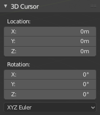
.
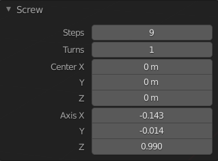
Bảng công cụ Đinh Vít (trong Chế Độ Biên Soạn).
- Số Phân/Bước (Steps)
Trường số này chỉ định số lần đẩy trồi thực hiện cho mỗi vòng quay 360 độ. Các bước được phân bổ đều bằng phương pháp chia 360 độ với số bước đã cho. Giá trị nhỏ nhất là 3; tối đa là 256 (Xin xem hình minh họa Bảng công cụ Đinh Vít (trong Chế Độ Biên Soạn).).
- Số Vòng Xoay (Turns)
Trường số này xác định số vòng quay sẽ được thực hiện. Blender sẽ cho thêm một vòng quay 360 độ đầy đủ mới cho mỗi số vòng quay chỉ định ở đây. Giá trị nhỏ nhất là 1; tối đa là 256. (Xin xem hình minh họa Bảng công cụ Đinh Vít (trong Chế Độ Biên Soạn)..)
- Trung Tâm X, Y, Z (Center X, Y, Z)
Các trường số này xác định tâm của vòng xoáy. Khi công cụ được kích hoạt lần đầu tiên thì nó sẽ sao chép vị trí XYZ (tọa độ toàn cầu) của con trỏ hiện có trong Cổng Nhìn 3D để bắt đầu thao tác. Bạn có thể xác định tọa độ con trỏ bằng cách sử dụng bảng Biến Hóa trong Cổng Nhìn 3D và nhập tọa độ Vị Trí Con Trỏ 3D. Bạn có thể điều chỉnh các tọa độ này một cách tương tác và xác định một vị trí khác cho tâm xoáy trong phiên sử dụng tương tác. (Xin xem hình minh họa Bảng công cụ Đinh Vít (trong Chế Độ Biên Soạn)..)
- Trục X, Y, Z (Axis X, Y, Z)
Ba trường số này thay đổi từ (-1.0 đến 1.0) và được hạn định trong các giới hạn đó. Các giá trị này tương ứng với các vectơ góc từ (-90 đến 90) độ. Tùy vào vị trí mà bạn khởi đầu, vị trí của con trỏ và thao tác Đối Tượng trong cổng nhìn, cùng các vị trí trục của nó trong không gian và tọa độ của Khung Nhìn Toàn Cầu, Blender sẽ cung cấp cho véctor Trục thích hợp giá trị 1, cung cấp cho vector góc của mặt cắt chiều hướng khởi thủy và cung cấp quá trình đẩy trồi một hướng bắt đầu dựa trên góc nhìn hiện tại. Blender sẽ cho phép bạn điều chỉnh các vectơ góc trục và bạn có thể hiệu chỉnh đối tượng của mình để có thể đảo ngược hướng của thao tác đinh vít (bằng cách đảo ngược vectơ góc của chiều cao), nghĩa là bạn có thể đảo ngược hướng thuận chiều kim đồng hồ và ngược chiều kim đồng hồ một số thao tác, và đồng thời điều chỉnh các véctơ góc của mặt cắt, uốn nó cho phù hợp. (Xin xem hình minh họa Bảng công cụ Đinh Vít (trong Chế Độ Biên Soạn)..)
Một Số Ví Dụ (Examples)
Ví Dụ cái Lò Xo (The Spring Example)
Mở Blender và xóa khối lập phương Cube mặc định.
Đổi góc nhìn từ phối cảnh sang trực giao bằng phím tắt Numpad5.
Thay đổi góc nhìn từ "Trực Giao của Người Dùng" thành "Trực Giao Trước", sử dụng phím tắt Numpad1. Bạn sẽ thấy các đường tọa độ X (đỏ) và Z (xanh lam).
Trong trường hợp bạn đã di chuyển con trỏ bằng cách nhấp vào bất kỳ đâu trên màn hình rồi thì hãy đặt lại con trỏ về Trung Tâm, sử dụng phím tắt Shift-S chọn "Con Trỏ về Tọa Độ Gốc Thế Giới" hoặc dùng bảng Biến Hóa, đặt con trỏ về ( 0, 0, 0) bằng cách đánh máy chữ trực tiếp vào vị trí của Con Trỏ 3D.
Cho thêm một vòng tròn bằng phím tắt Shift-A .
Rotate this circle using the shortcut R X 9 0 and Return.
Apply the Rotation using Ctrl-A and choosing Rotation.
Move this circle three units on the X axis to the left; you can use the shortcut Ctrl while selecting with the mouse using the standard transform widgets (clicking on the red arrow shown with the object and moving while using shortcut Ctrl until the info in the top left corner of the 3D Viewport displays
D. -3.0000 (3.0000) Global), or press the shortcut G X Minus 3 and Return. You can use the Transform panel, and type Minus 3 and Return in the Location too. (See the Fig. Vòng tròn đặt tại X (-3, 0, 0)..)You will have to scale the circle using the shortcut S Period 5, then Return.
Now enter Edit Mode using shortcut Tab.
Deselect all vertices using the shortcut Alt-A.
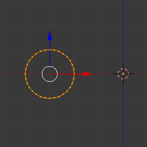
Vòng tròn đặt tại X (-3, 0, 0).
Các bước sau đây giải thích phương pháp tạo một véctơ chiều cao:
Select an edge from the circle and duplicate the edge with Shift-D and move the edge to the right of the circle. This edge will be used as the first height and angle vector of the screw.
With one of the vertices selected, in the Transform panel give the vertex the global position to the XYZ coordinates of (-2, 0, -1).
Select the other vertex, and again, set its XYZ coordinates to (-2, 0, 1). This will create a straight vertical line with 2 units of height.
Select everything again with the shortcut A. (See Fig. Mặt cắt và véctor được tạo ra..)
Một lần nữa, đặt con trỏ ở trung tâm.
At this point, Save the blend-file to reuse the spring for another exercise. You can name it e.g. "screw spring example.blend".
Click Screw and adjust the Steps and Turns as you like to create a nice spring.
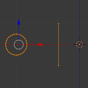
Mặt cắt và véctor được tạo ra.
Thuận Chiều Kim Đồng Hồ & Ngược Chiều Kim Đồng Hồ dùng Ví Dụ Lò Xo (Clockwise & Counterclockwise using the Spring Example)
Still in the interactive session of the Screw tool, you will see that the Z axis Value of the Screw panel is set to 1.000. LMB click in the middle of the Value and set this value to -1.000. At first, the spring was being constructed in a counterclockwise direction, and you reverted the operation 180 degrees in the Z axis. This is because you have changed the angular vector of the height you have given to Blender to the opposite direction (remember, -90 to 90 = 180 degrees ?). See Fig. Chiều hướng của lò xo..
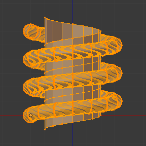
Hướng ngược chiều kim đồng hồ. |
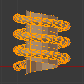
Flipped to Clockwise direction. |
It is also important to note that this vector is related to the same height vector axis used for the extrusion and you have created a parallel line with the Z axis, so, the sensibility of this vector is in practical sense reactive only to negative and positive values because it is aligned with the extrusion axis. Blender will clamp the positive and negative to its maximum values to make the extrusion follow a direction, even if the profile starts reverted. The same rule applies to other global axes when creating the object for the Screw tool; this means if you create your object using the Top View with a straight parallel line following another axis (for the Top View, the Y axis), the vector that gives the height for extrusion will also change abruptly from negative to positive and vice versa to give the extrusion a direction, and you will have to tweak the corresponding axis accordingly to achieve the clockwise and counterclockwise effect.
Ghi chú
Vectors that are not Parallel with Blender Axis
The high sensibility for the vector does not apply to vectors that give the Screw tool a starting angle (e.g. any non-parallel vector), meaning Blender will not need to clamp the values to stabilize a direction for the extrusion, as the inclination of the vector will be clear for Blender and you will have the full degree of freedom to change the vectors. This example is important because it only changes the direction of the profile without the tilt and/or bending effect, as there is only one direction for the extrusion, parallel to one of the Blender Axes.
Uốn các Mặt Cắt bằng việc sử dụng Ví Dụ Lò Xo (Bending the Profiles using the Spring Example)
Still using the spring example, you can change the remaining vector for the angles that are not related to the extrusion axis of the spring. Bending the spring with the remaining vectors and creating a profile that will also open and/or close because of the change in starting angular vector values. What really is changed is the starting angle of the profile before the extrusions. It means that Blender will connect each of the circles inclined with the vector you have given. The images below show two bent meshes using the axis vectors and the spring example. See Fig. Khung lưới được uốn cong.. These two meshes generated with the Screw tool were created using the Top Orthographic View.
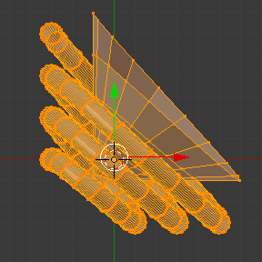
The Axis will give the profile a starting vector angle. |
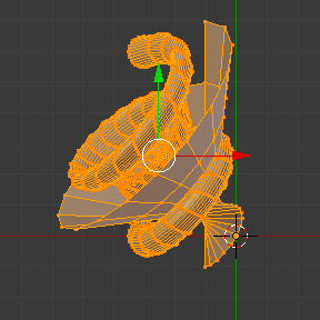
The vector angle is maintained along the extrusions. |
Tạo Trục Đinh Vít Hoàn Hảo (Creating Perfect Screw Spindles)
Using the spring example, it is easy to create perfect screw spindles (like the ones present in normal screws that you can buy in hardware stores). Perfect screw spindles use a profile with the same height as its vector, and the beginning and ending vertex of the profile are placed at a straight parallel line with the axis of extrusion. The easiest way of achieving this effect is to create a simple profile where the beginning and ending vertices create a straight parallel line. Blender will not take into account any of the vertices present in the middle but those two to take its angular vector, so the spindles of the screw (which are defined by the turns value) will assembly perfectly with each other.
Open Blender and click on File located in the header of the Info editor again, choose Open Recent and select the file you saved for this exercise. All of the things will be placed exactly the way you saved before. Choose the last saved blend-file; in the last exercise, you gave it the name "screw spring example.blend".
Press the shortcut Alt-A to deselect all vertices.
Press the shortcut B, and Blender will change the cursor; you are now in box selection mode.
Open a box that selects all of the circle vertices except the two vertices you used to create the height of the extrusions in the last example.
Use the shortcut X to delete them.
Press the shortcut A to select the remaining vertices.
Chọn: chọn menu: Trình đơn ngữ cảnh -> Chia nhỏ.
Now, click with the LMB on the middle vertex.
Move this vertex using the shortcut G X Minus 1 and Return. See Fig. Profile for a perfect screw spindle..
At this point, you can save this blend-file to recycle the generated Screw for another exercise; click with LMB on File -- it is in the header of the Info editor (at the top left side), and choose Save as. You can name it e.g. "screw hardware example.blend".
Press the shortcut A to select all the vertices again.
Bây giờ nhấn Đinh Vít.
Change Steps and Turns as you like. Fig. Khung lưới sinh tạo ra. shows you an example of the results.
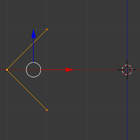
Profile for a perfect screw spindle. The starting and ending vertices are forming a parallel line with the Blender Axis. |
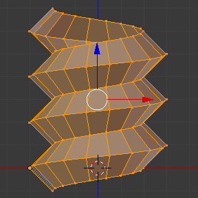
Khung lưới sinh tạo ra. You can use this technique to perform normal screw modeling. |
Fig. Dốc. shows an example using a different profile, but maintaining the beginning and ending vertices at the same position. The generated mesh looks like a medieval ramp!
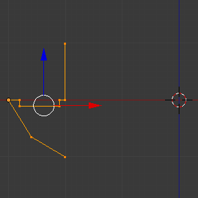
Profile with starting and ending vertices forming a parallel line with the Blender Axis. |
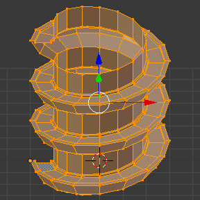
Generated mesh with the profile at the left. The visualization is inclined a bit. |
As you can see, the Screw spindles are perfectly assembled with each other, and they follow a straight line from top to bottom. You can also change the clockwise and counterclockwise direction using this example, to create right and left screw spindles. At this point, you can give the screw another dimension, changing the Center of the spin extrusion, making it more suitable to your needs or calculating a perfect screw and merging its vertices with a cylinder, modeling its head, etc.
Một cái Đầu Vít (A Screw Tip)
As explained before, the Screw tool generates clean and simple meshes to deal with; they are light, well-connected and are created with very predictable results. This is due to the Blender calculations taking into account not only the height of the vector, but also its starting angle. It means that Blender will connect the vertices with each other in a way that they follow a continuous cycle along the extruded generated profile.
In this example, you will learn how to create a simple Screw Tip (like the ones used for wood; as shown in the example at the beginning of this page). To make this new example as short as possible, it will recycle the last example (again).
Open Blender and click on File located in the header of the Info editor again; choose Open Recent and the file saved for this exercise. All of the things will be placed exactly the way you saved before. Choose the last saved blend-file; from the last exercise, which is named "screw hardware example.blend".
Move the upper vertex and move a bit to the left, but no more than you have moved the last vertex. (See Fig. Profile with a starting vector angle..)
Press the shortcut A twice to deselect and select all.
Press the shortcut Shift-S and select Cursor to Center.
Nhấn Đinh Vít.
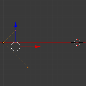
Profile with a starting vector angle. |
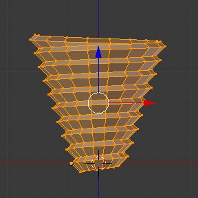
Generated mesh with the profile. |
As you can see in Fig. Generated mesh with the profile., Blender follows the basic angular vector of the profile, and the profile basic angle determines whether the extruded subsequent configured turns will open or close the resulting mesh following this angle. The vector of the extrusion angle is determined by the starting and ending vertex of the profile.