数据传递修改器
数据传输修改器将几种类型的数据从一个网格传输到另一个网格。 数据类型包括顶点组,UV贴图,顶点颜色,自定义法线等。
Transfer works by generating a mapping between source mesh's elements (vertices, edges, etc.) and destination ones, either on a one-to-one basis, or mapping several source elements to a single destination one, using interpolation.
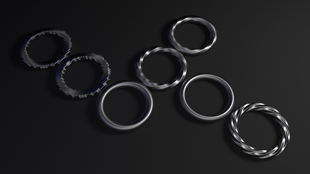
物体间传输法线,见 样例 blend 文件。
See also
选项
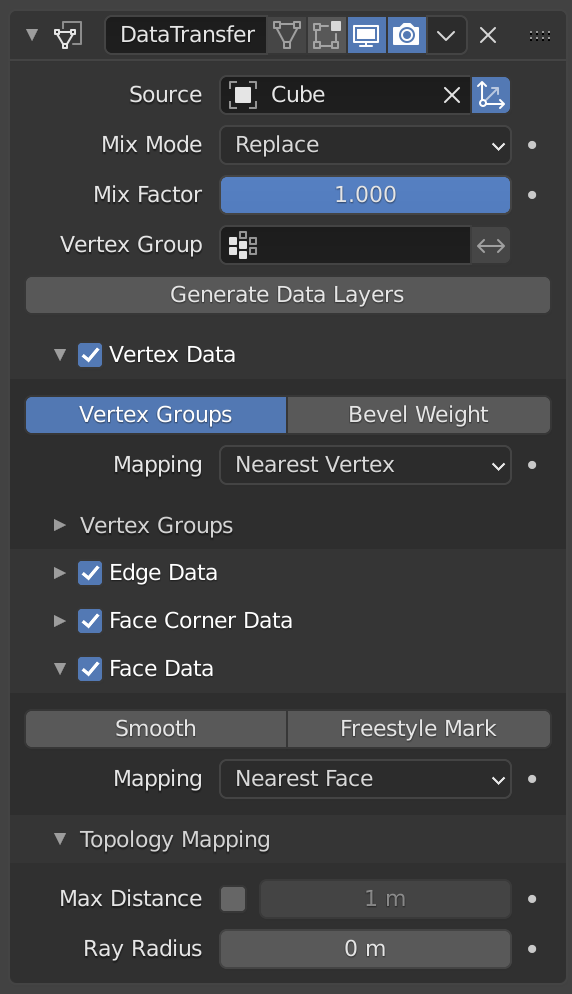
数据传递修改器。
- 源
要复制数据的网格物体。
如果未设置字段右侧的按钮,则在生成映射时会在全局空间中考虑来源与目标几何体,否则将在局部空间中对它们进行计算(即,好像两个物体的原点位于同一位置)。
- 混合模式
控制如何影响目标数据:
- 全部
替换目标物体中的所有内容(注意: 仍然使用 混合系数 )
- 上限阈值
只有当目标值高于给定的阈值 混合系数 时,才替换目标值。如何解释该阈值取决于数据类型,请注意,对于布尔值,此选项将充当逻辑与。
- 下限阈值
只有当目标值低于给定的阈值 混合系数 时,才替换目标值。如何解释该阈值取决于数据类型,请注意,对于布尔值,此选项将充当逻辑或。
- 混合,添加,相减, 相乘
应用该操作,将使用混合系数来控制源物体或目标物体数值使用的程度。仅适用于几种元素类型(顶点组,顶点颜色)。
- 混合系数
将多少传输的数据混合到现有数据中(不受所有数据类型的支持)。
- 顶点组
Allows per-element fine control of the mix factor. Vertex group influence can be reverted using the small "arrow" button to the right.
- 生成数据层
这个修改器不能生成所需的数据层本身。如果需要,一旦选择了数据源数据集,该按钮将被用来生成匹配的目标层。
选择要传输的数据
To keep the size of the modifier reasonable, the kind of elements to be affected must be selected first (vertices, edges, face corners and/or faces).
- 映射类型
How is generated the mapping between those source and destination elements. Each type has its own options, see Geometry Mapping below for details.
- 数据类型
切换按钮的左列,以选择要传输的数据类型。
- 多层数据类型选项
在这种情况下(顶点组、顶点颜色、UVs),一个可以选择源层转移(通常,要么是所有的,或一个指定的),以及如何影响目标物体(通过匹配名字,匹配顺序/位置,或者通过手动指定目的层,选择一个源,)。
- UV孤岛处理精简
此设置目前只影响UV的传递。它允许避免一个给定的目标面获得来自不同源UV岛的UV坐标。将其保持在0.0意味着完全不处理岛屿。通常,像0.02这样的小值就足以获得良好的结果,但是如果您要从一个非常多面的的源映射到一个非常低面的目标,那么您可能必须大幅提高它。
使用
在使用这个修改器时要记住的第一个关键事项是它将 不会 创建目标数据层。为此,一旦选择了传输的源数据集, 生成数据层 按钮应始终开启。这也应该很好理解,在目标网格上创建的这些数据层 不是 修改器堆栈的一部分,这意味着如果删除了修改器,或者更改源数据选择,它们仍会继续存在。
几何映射
几何映射是一个给定的目标网格如何与源网格相关联。在这个过程中,一个目标顶点/边缘/…获取指定的源网格作为其数据源的一部分。要想用这个修改器得到良好的效果,理解透这个主题是至关重要的。
- 拓扑
The simplest option, expects both meshes to have identical number of elements, and match them by order (indices). Useful e.g. between meshes that were identical copies, and got deformed differently.
- 一对一映射
Those always select only one source element for each destination one, often based on shortest distance.
- 顶点
- 最近的点
使用源物体最近的顶点数据。
- 最近的边顶点
使用源物体最近边的顶点数据。
- 最近的面顶点
使用源物体最近面的顶点数据。
- 边
- 最近的顶点
使用源物体中距离目标边最近的顶点所在边的数据。
- 最近的边
用源物体中距离目标边最近的边线数据(使用边线的中点计算)。
- 最近的面边
使用源物体最近面的最近边缘(使用边缘的中点)。
- 面拐
A face corner is not a real element by itself, it's some kind of split vertex attached to a specific face. Hence both vertex (location) and face (normal, ...) aspects are used to match them together.
- 最近的拐角和最佳匹配法线
从最近的源拐角中,选取与目标拐点 拆分 法向最相近的源拐角数据。
- 最近的拐角和最佳匹配面法线
从最近的源拐角中,选取与目标拐角 面 法向最相近的源拐角数据。
- 最近面上的最近拐角
使用最近源面的最近拐角数据。
- 面
- 最近的面
使用最近的源面数据。
- 最佳法线匹配
使用与目标法向最匹配的源面数据。
- 插值映射
Those use several source elements for each destination one, interpolating their data during the transfer.
- 顶点
- 最近边插值
使用最近来源边的最近点数据,对来源边的两个顶点数据插值。
- 最近面插值
使用最近来源面的最近点数据,对来源面的所有顶点数据插值。
- 投影面插值
使用目标顶点沿自身法向投影到来源面的点数据,对该来源面的所有顶点数据插值。
- 边
- 投影边插值
这是一个采样过程。沿着目标的边缘投射几条光线(插值两条边的顶点法线),如果足够多的光线射入一个源的边缘,所有命中源边缘的数据都被插值到目标的边缘。
- 面拐
A face corner is not a real element by itself, it's some kind of split vertex attached to a specific face. Hence both vertex (location) and face (normal, ...) aspects are used to match them together.
- 最近面插值
使用最近的源面的最近点数据,对源面的所有拐角插值。
- 投影面插值
使用目标拐角沿自身法向投影到来源面的点数据,对该来源面的拐角数据插值。
- 面
- 投影面插值
这是一个采样过程。从整个目标面投射几束光线(沿着它自己的法线),如果有足够多的光线照射到源面,所有被照射的源面数据都被插值到目标面。
拓扑映射
- 最大距离
When the "pressure stylus" icon button to the right is enabled, this is the maximum distance between source and destination to get a successful mapping. If a destination element cannot find a source one within that range, then it will get no transferred data.
这样可以将一个小的细分的模型传递到更复杂的模型上(比如将手部模型传递到 "整体模型" 上)。
- 光线半径
The starting ray radius to use when Ray Casting against vertices or edges. When transferring data between meshes Blender performs a series of ray casts to generate mappings. Blender starts with a ray with the radius defined here, if that does not return a hit then the radius is progressively increased until a positive hit or a limit is reached.
This property acts as an accuracy/performance control; using a lower ray radius will be more accurate however, might take longer if Blender has to progressively increase the limit. Lower values will work better for dense meshes with lots of detail while larger values are probably better suited for simple meshes.