Curves and Surfaces
Curves and surfaces are objects like meshes, but differ in that they are expressed in terms of mathematical functions, rather than as a series of points.
Blender implements B�zier and Non Uniform Rational B-Splines (NURBS) curves and surfaces. Both, though following different mathematical laws, are defined in terms of a set of "control vertices" which define a "control polygon." The way the curve and the surface are interpolated (B�zier) or attracted (NURBS) by these might seem similar, at first glance, to Catmull-Clark subdivision surfaces.
When compared to meshes, curves and surfaces have both advantages and disadvantages. Because curves are defined by less data, they produce nice results using less memory at modelling time, whereas the demands increase at rendering time.
Some modelling techniques, such as extruding a profile along a path, are only possible with curves. But the very fine control available on a per-vertex basis on a mesh, is not possible with curves.
There are times when curves and surfaces are more advantageous than meshes, and times when meshes are more useful. If you have read the previous Chapter, and if you read this you will be able to choose whether to use meshes or curves.
Curves
Relevant to Blender v2.31
This section describes both B�zier and NURBS curves, and shows a working example of the former.
B�ziers
B�zier curves are the most commonly used type for designing letters or logos. They are also widely used in animation, both as paths for objects to move along and as IPO curves to change the properties of objects as a function of time.
A control point (vertex) of a B�zier curve consists of a point and two handles. The point, in the middle, is used to move the entire control point; selecting it also selects the other two handles, and allows you to move the complete vertex. Selecting one or two of the other handles allows you to change the shape of the curve by dragging the handles.
A B�zier curve is tangent to the line segment which goes from the point to the handle. The 'steepness' of the curve is controlled by the handle's length.
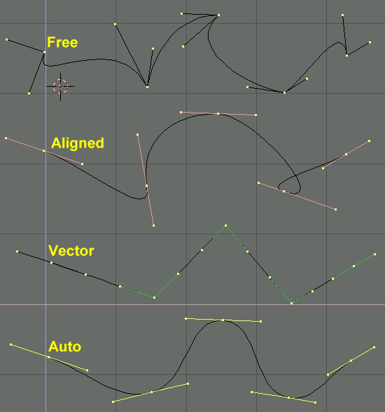
There are four types of handles (Figure 1):
Free Handle (black). This can be used in any way you wish. Hotkey: HKEY (toggles between Free and Aligned);
Aligned Handle (purple). These handles always lie in a straight line. Hotkey: HKEY (toggles between Free and Aligned);
Vector Handle (green). Both parts of a handle always point to the previous handle or the next handle. Hotkey: VKEY;
Auto Handle (yellow). This handle has a completely automatic length and direction, set by Blender to ensure the smoothest result. Hotkey: SHIFT-H.
Handles can be grabbed, rotated and scaled exactly as ordinary vertices in a mesh would.
As soon as the handles are moved, the type is modified automatically:
Auto Handle becomes Aligned;
Vector Handle becomes Free.
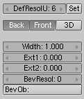
Although the B�zier curve is a continuous mathematical object it must nevertheless be represented in discrete form from a rendering point of view.
This is done by setting a resolution property, which defines the number of points which are computed between every pair of control points. A separate resolution can be set for each B�zier curve (Figure 2).
NURBS
NURBS curves are defined as rational polynomials, and are more general, strictly speaking, than conventional B-Splines and B�zier curves inasmuch they are able to exactly follow any contour. For example a B�zier circle is a polynomial approximation of a circle, and this approximation is noticeable, whereas a NURBS circle is exactly a circle. NURBS curves have a large set of variables, which allow you to create mathematically pure forms (Figure 3). However, working with them requires a little more theory:
Knots. Nurbs curves have a knot vector, a row of numbers that specifies the parametric definition of the curve. Two pre-sets are important for this. Uniform produces a uniform division for closed curves, but when used with open ones you will get "free" ends, which are difficult to locate precisely. Endpoint sets the knots in such a way that the first and last vertices are always part of the curve, which makes them much easier to place;
Order. The order is the 'depth' of the curve calculation. Order '1' is a point, order '2' is linear, order '3' is quadratic, and so on. Always use order '5' for Curve paths because it behaves fluidly under all circumstances, without producing irritating discontinuities in the movement. Mathematically speaking this is the order of both the Numerator and the Denominator of the rational polynomial defining the NURBS;
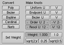
Weight. Nurbs curves have a 'weight' per vertex - the extent to which a vertex participates in the "pulling" of the curve.
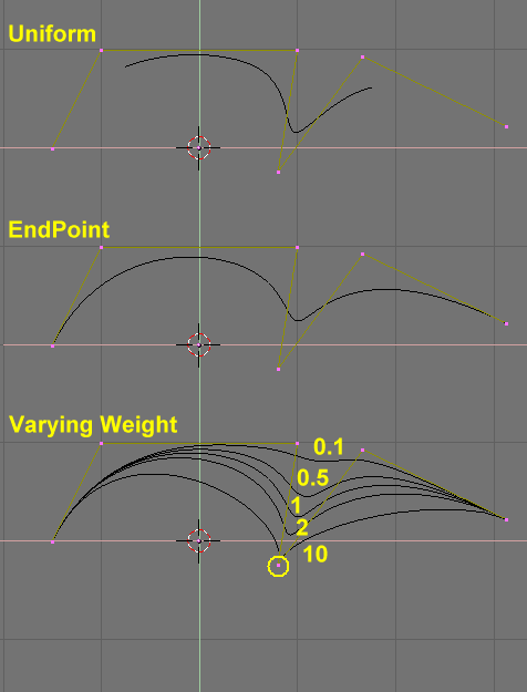
Figure 4 shows the Knot vector settings as well as the effect of varying a single knot weight. As with B�ziers, the resolution can be set on a per curve basis.
Working example
Blender's curve tools provide a quick and easy way to build great looking extruded text and logos. We will use these tools to turn a rough sketch of a logo into a finished 3D object.
Figure 5 shows the design of the logo we will be building.
First, we will import our original sketch so that we can use it as a template. Blender supports TGA, PNG, and JPG format images. To load the image, select the View>>Background Image... menu entry of the 3D Window you are using. A transparent panel will appear, allowing you to select a picture to use as a background. Activate the BackGroundPic button and use the LOAD button to locate the image you want to use as a template (Figure 6). You can set the "strength" of the background pic with the Blend slider.
Get rid of the Panel with ESC or by pressing the X button in the panel header (Figure 7). You can hide the background image when you are finished using it by returning to the Panel and deselecting the BackGroundPic button.
Add a new curve by pressing SPACE>>Curve>>Bezier Curve. A curved segment will appear and Blender will enter EditMode. We will move and add points to make a closed shape that describes the logo you are trying to trace.
You can add points to the curve by selecting one of the two endpoints, then holding CTRL and clicking LMB. Note that the new point will be connected to the previously selected point. Once a point has been added, it can be moved by selecting the control vertex and pressing GKEY. You can change the angle of the curve by grabbing and moving the handles associated with each vertex (Figure 8).
You can add a new point between two existing points by selecting the two points and pressing WKEY>>Subdivide (Figure 9).
Points can be removed by selecting them and pressing XKEY>>Selected. To cut a curve in two, select two adjacent control vertices and press XKEY>>Segment.
To make sharp corners, select a control vertex and press VKEY. You will notice that the color of the handles changes from purple to green (Figure 10). At this point, you can move the handles to adjust the way the curve enters and leaves the control vertex (Figure 11).
To close the curve and turn it into a single continuous loop, select at least one of the control vertices on the curve and press CKEY. This will connect the last point in the curve with the first one (Figure 12). You may need to manipulate additional handles to get the shape you want.
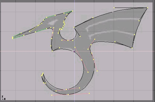
Leaving EditMode with TAB and entering shaded mode with ZKEY should reveal that the curve renders as a solid shape (Figure 13). We want to cut some holes into this shape to represent the eyes and wing details of the dragon.
 | Surfaces and Holes |
|---|---|
When working with curves, Blender automatically detects holes in the surface and handles them accordingly to the following rules. A closed curve is always considered the boundary of a surface and hence rendered as a flat surface. If a closed curve is completely included within another one, the inner one is subtracted from the outer one, effectively defining a hole. |
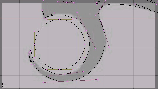
Return to wireframe mode with ZKEY and enter EditMode again with TAB. While still in EditMode, add a circle curve with SPACE>>Curve>>Bezier Circle (Figure 14). Scale the circle down to an appropriate size with SKEY and move it with GKEY.
Shape the circle using the techniques we have learned (Figure 15). Remember to add vertices to the circle with WKEY>>Subdivide.
Create a wing cutout by adding a B�zier circle, converting all of the points to sharp corners, and then adjusting as necessary. You can duplicate this outline to save time when creating the second wing cutout. To do so, make sure no points are selected, then move the cursor over one of the vertices in the first wing cutout and select all linked points with LKEY (Figure 16). Duplicate the selection with SHIFT-D and move the new points into position.
To add more geometry that is not connected to the main body (placing an orb in the dragon's curved tail for example), use the SHIFT-A menu to add more curves as shown in Figure 17.
Now that we have the curve, we need to set its thickness and beveling options. With the curve selected, go to the EditButtons (F9) and locate the Curves and Surface panel. The Ext1 parameter sets the thickness of the extrusion while Ext2 sets the size of the bevel. BevResol sets how sharp or curved the bevel will be.
Figure 18 shows the settings used to extrude this curve.
| From Curves to Meshes |
|---|---|
To perform more complex modelling operations, convert the curve to a mesh with ALT-C>>Mesh. Note that this is a one-way operation: you cannot convert a mesh back into a curve. |
When your logo model is complete, you can add materials and lights and make a nice rendering (Figure 19).