Navigating in 3D Space
Relevant to Blender v2.31
Blender lets you work in three-dimensional space, but our monitor screens are only two-dimensional. To be able to work in three dimensions, you must be able to change your viewpoint as well as the viewing direction of the scene. This is possible in all of the 3D Viewports.
Even if we will describe the 3D Viewport Window, most non-3D windows use an equivalent series of functions, for example it is even possible to translate and zoom a Buttons Window and its Panels.
The viewing direction (rotating)
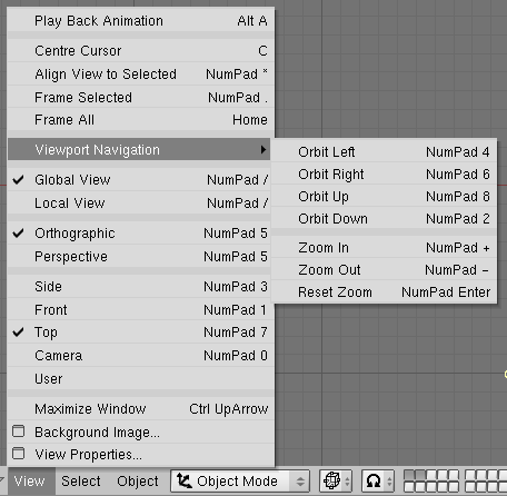
Blender provides three default viewing directions: Side, Front, and Top. As Blender uses a right-hand coordinate system with the Z axis pointing upwards, "side" corresponds to looking along the X axis, in the negative direction; "front" along the Y axis; and "top" along the Z axis. You can select the viewing direction for a 3D Viewport with the View Menu entries (Figure 13) or by pressing the hotkeys NUM3 for "side", NUM1 for "front", and NUM7 for "top".
 | Hotkeys |
|---|---|
Remember that most hotkeys affect the window that has focus, so check that the mouse cursor is in the area you want to work in before your use the hotkeys! |
Apart from these three default directions, the view can be rotated to any angle you wish. Click and drag MMB on the Viewport's area: If you start in the middle of the window and move up and down or left and right, the view is rotated around the middle of the window. If you start at the edge and don't move towards the middle, you can rotate around your viewing axis. Play around with this function until you get the feeling for it.
To change the viewing angle in discrete steps, use NUM8 and NUM2, which correspond to vertical MMB dragging. Or use NUM4 and NUM6, which correspond to horizontal MMB dragging.
Translating and Zooming the View
To translate the view, hold down SHIFT and drag MMB in the 3D Viewport. For discrete steps, use the hotkeys CTRL-NUM8, CTRL-NUM2, CTRL-NUM4 and CTRL-NUM6 as with rotating.
You can zoom in and out by holding down CTRL and dragging MMB. The hotkeys are NUM+ and NUM-. The View>>Viewport Navigation sub-menu holds these functions too.
| Wheel Mouse |
|---|---|
If you have a wheel mouse, you can perform all of the actions that you would do with NUM+ and NUM- by rotating the wheel (MW). The direction of rotation selects the action. |
| If You Get Lost... |
|---|---|
If you get lost in 3D space, which is not uncommon, two hotkeys will help you: HOME changes the view so that you can see all objects (View>>Frame All Menu entry,) while NUM. zooms the view to the currently selected objects (View>>Frame Selected Menu entry.) |
Perspective and Orthographic Projection
Each 3D Viewport supports two different types of projection. These are demonstrated in Figure 14: orthographic (left) and perspective (right).
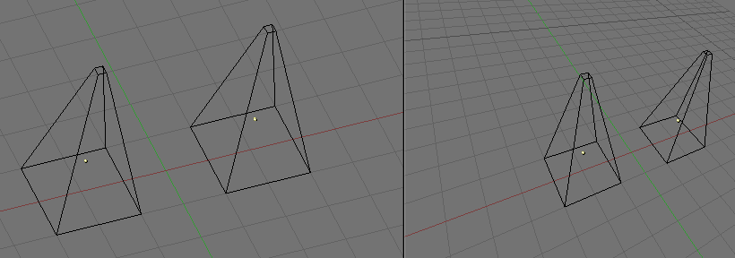
Our eye is used to perspective viewing because distant objects appear smaller. Orthographic projection often seems a bit odd at first, because objects stay the same size independent of their distance: It is like viewing the scene from an infinitely distant point. Nevertheless, orthographic viewing is very useful (it is the default in Blender and most other 3D applications), because it provides a more "technical" insight into the scene, making it easier to draw and judge proportions.
| Perspective and Orthographic |
|---|---|
Perspective view is geometrically constructed this way: you have a scene in 3D and you are an observer palced in a point O. The 2D perspective scene is built by placing a plane, a sheet of paper where the 2D scene is to be drawn in front of point O, perpendicular to the viewing direction. For each point P in the 3D scene a line is drawn, passing from O and P. The intersection point S between this line and the plane is the perspective projection of that point. By projecting all points P of the scene you get a perspective view. In an orthographic projection, also called "orthonormal", on the other hand, you have a viewing direction but not a viewing point O. The line is then drawn through point P so that it is parallel to the viewing direction. The intersections S between the line and the plane is the orthographic projection. And by projecting all point P of the scene you get the orthographic view. |
To change the projection for a 3D Viewport, choose View>>Orthographic or View>>Perspective Menu entries (Figure 13 in the Section called The viewing direction (rotating)). The hotkey NUM5 toggles between the two modes.
| Camera projection |
|---|---|
Note that changing the projection for a 3D Viewport does not affect the way the scene will be rendered. Rendering is in perspective by default. If you need to create an Orthographic rendering, select the camera and press Ortho in the EditButtons (F9) Camera Panel. |
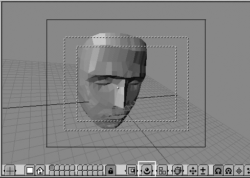
The View>>Camera Menu entry sets the 3D Viewport to camera mode (Hotkey: NUM0). The scene is then displayed as it will be rendered later (see Figure 15): the rendered image will contain everything within the outer dotted line. Zooming in and out is possible in this view, but to change the viewpoint, you have to move or rotate the camera.
Draw mode
Depending on the speed of your computer, the complexity of your Scene, and the type of work you are currently doing, you can switch between several drawing modes:
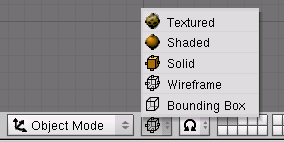
Textured - Attempts to draw everything as completely as possible, though it is still no alternative to rendering. Note that if you have no lighting in your scene, everything will remain black.
Shaded - Draws solid surfaces including the lighting calculation. As with textured drawing, you won't see anything without lights.
Solid - Surfaces are drawn as solids, but the display also works without lights.
Wireframe - Objects only consist of lines that make their shapes recognizable. This is the default drawing mode.
Bounding Box - Objects aren't drawn at all; instead this mode shows only the rectangular boxes that correspond to each object's size and shape.
The drawing mode can be selected with the appropriate Menu Button in the header (Figure 16) or with hotkeys: ZKEY toggles between wireframe and solid display, SHIFT-Z toggles between wireframe and shaded display.
Local view
When in local view, only the selected objects are displayed, which can make editing easier in complex scenes. To enter local view, first select the objects you want (see the Section called Selecting objects in the chapter called ObjectMode) and then use the View>>Local View Menu entry; use the View>>Global View Menu entry to go back to Global View. (Figure 13 in the Section called The viewing direction (rotating)). The hotkey is NUM/, which toggles Local/Global View.
The layer system
3D scenes often become exponentially more confusing with growing complexity. To get this under control, objects can be grouped into "layers," so that only the layers you select are displayed at any one time. 3D layers differ from the layers you may know from 2D graphics applications: they have no influence on the drawing order and are there (except for some special functions) solely to provide the modeler with a better overview.
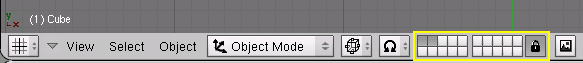
Blender provides 20 layers; you can choose which are to be displayed with the small unlabeled buttons in the header (Figure 17). To select only one layer, click the appropriate button with LMB; to select more than one, hold SHIFT while clicking.
To select layers via the keyboard, press 1KEY to 0KEY (on the main area of the keyboard) for layers 1 through 10 (the top row of buttons), and ALT-1 to ALT-0 for layers 11 through 20 (the bottom row). The SHIFT key for multiple selection works for these hotkeys too.
By default, the lock button directly to the right of the layer buttons is pressed; this means that changes to the viewed layers affect all 3D Viewports. To select only certain layers in one window, deselect locking first.
To move selected objects to a different layer, press MKEY, select the layer you want from the pop-up dialog, then press the Ok button.