Shading
Viewport Shading
Reference
| Header: |
|---|
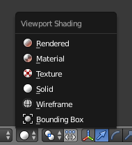
The Viewport Shading menu.
Shading refers to the way objects are drawn and lit in the 3D View.
- Bounding Box
- Only shows rectangular boxes that outline an object’s size and shape.
- Wireframe
- Objects appear as a mesh of lines representing the edges of faces and surfaces.
- Solid
- The default drawing mode using solid colored surfaces and simple lighting.
- Textured
- Shows meshes with an image applied using the mesh’s active UV map. For Cycles materials, the image is the last one selected in the Node Editor. For other render engines, the UV map’s applied face texture will be shown.
- Material
- A fast approximation of the applied material.
- Rendered
- An accurate representation using the selected Render Engine and lit with the visible scene lights.
Except for Rendered, these shading modes are not dependent on light sources in the scene. Instead they use a simple default lighting adjusted by the Solid OpenGL Lights controls on the System tab of the User Preferences editor.
The viewport shading controls the appearance of all objects in a scene, but this can be overridden for individual objects using the Display panel in their Object Properties.
Keyboard Shortcuts
| Switches between Wireframe and Solid draw modes. | Z |
|---|---|
| Switches between the current and Rendered draw modes. | Shift-Z |
| Switches between Solid and Textured draw modes. | Alt-Z |
Shading Panel
Reference
| Panel: |
|---|

3D View Shading panel.
The shading panel in the Properties Region provides additional control over the way objects in the 3D View appear.
- Textured Solid
- Display assigned face textures in the Solid shading mode. (not available in the Cycles Renderer).
- Shadeless
- Textured mode only – Draws textures without shading. Its most common use case is texture painting.
- Matcap
- “Matcaps” are images mapped on a normal. It provides a quick way to define visible material properties for modeling and sculpting. Because Matcap rendering fully bypasses the material shader code, it’s a very fast rendering option. The selected Matcap is a setting per 3D View. This way you can have multiple views drawing different Matcaps. (Solid Viewport shading only).
- Backface Culling
- Only show the front side of faces. Use this to find faces flipped the wrong way, especially when exporting to programs that use single sided drawing.
- Hidden Wire
Show only front-facing wireframes. This is useful for a retopology workflow. (Mesh, Edit Mode only).
Tip: Optimally this could be combined with the X-Ray display setting.
- Depth of Field
- Simulates a camera’s focal blur effect in the 3D View. This is only visible in a camera view. Control the effect using these options in the Properties Tab of the active camera: Focal Length, Sensor Size, Focus Object or Focus Distance, and Viewport F-stop.
- Ambient Occlusion
Improves the realism of the viewport image by simulating the darkening effect that occurs in crevices and corners. This is done by ray casting in screen space. Typically such effects are rendered at higher quality, but this is a quick real-time preview which can help when modeling or sculpting.
- Strength
- This factor directly multiplies the computed color of the effect, so increasing this value gives a stronger effect.
- Distance
- The maximum world space distance the effect is computed in. I.e. how far out of the corners does the effect extend.
- Attenuation
- How strongly the effect attenuates with distance. Increasing this makes far away surfaces contribute less to the effect. Use this to get rid of some banding artifacts.
- Samples
- The number of samples used for the effect. Low numbers produce a grainy effect, but the actual number used is squared so use high numbers with caution.
- Color
- Color of the effect, can be modified to give a different feel, from ambient lighting to dirt/rust.