Data Transfer Modifier
The Data Transfer Modifier transfers several types of data from one mesh to another. Data types include vertex groups, UV maps, vertex colors, custom normals…
Transfer works by generating a mapping between source mesh’s items (vertices, edges, etc.) and destination ones, either on a one-to-one basis, or mapping several source items to a single destination one by interpolated mapping.
Transferring normals between objects, see example blend-file.
Options
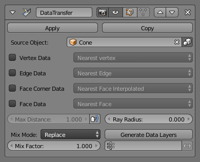
Data Transfer Modifier.
- Source Object
Mesh object to copy data from.
If the button to the right of the field is unset, source and destination geometries are considered in global space when generating the mapping, otherwise they are evaluated in local space (i.e. as if both object’s origins were at the same place).
- Max Distance
When the “hand and bulged in blue line” icon button to the right is enabled, this is the maximum distance between source and destination to get a successful mapping. If a destination item cannot find a source one within that range, then it will get no transferred data.
This allows to transfer a small sub-detailed mesh onto a more complete one (e.g. from a “hand” mesh towards a “full body” one).
- Ray Radius
- For ray-casting-based mapping methods, the radius of the cast rays. Especially important for 1D and 2D items (i.e. vertices and edges), without some width there would be nearly no ray-casting matches…
- Mix Mode
Controls how destination data are affected:
- All
- Replaces everything in destination (note that Mix Factor is still used).
- Above Threshold
- Only replaces destination value if it’s above given threshold Mix Factor. How that threshold is interpreted depends on data type, note that for boolean values this option fakes a logical AND.
- Below Threshold
- Only replaces destination value if it’s below given threshold Mix Factor. How that threshold is interpreted depends on data type, note that for boolean values this option fakes a logical OR.
- Mix, Add, Subtract, Multiply
- Apply that operation, using mix factor to control how much of source or destination value to use. Only available for a few types (vertex groups, vertex colors).
- Mix Factor
- How much of the transferred data gets mixed into existing one (not supported by all data types).
- Vertex Group
- Allows per-item fine control of the mix factor. Vertex group influence can be reverted using the small “arrow” button to the right.
- Generate Data Layers
- This modifier cannot generate needed data layers itself. Once the set of source data to transfer is selected, this button shall be used to generate matching destination layers.
Selection of Data to Transfer
To keep the size of the modifier reasonable, the kind of items to be affected must be selected first (vertices, edges, face corners and/or faces).
- Mapping Type
- How is generated the mapping between those source and destination items. Each type has its own options, see Geometry Mapping below for details.
- Data Types
- The left column of toggle buttons, to select which data types to transfer.
- Multi-layers Data Types Options
- In those cases (vertex groups, vertex colors, UVs), one can select which source layers to transfer (usually, either all of them, or a single specified one), and how to affect destination (either by matching names, matching order/position, or, if a single source is selected, by specifying manually destination layer).
- Islands Handling Refinement
- This setting only affects UV transfer currently. It allows to avoid a given destination face to get UV coordinates from different source UV islands. Keeping it at 0.0 means no island handling at all. Typically, small values like 0.02 are enough to get good results, but if you are mapping from a very high-poly source towards a very low-poly destination, you may have to raise it quite significantly.
Usage
First key thing to keep in mind when using this modifier is that it will not create destination data layers. Generate Data Layers button shall always be used for this purpose, once set of source data to transfer is selected. It should also be well understood that creating those data layers on destination mesh is not part of the modifier stack, which means e.g. that they will remain even once the modifier is deleted, or if source data selection is modified.
Geometry Mapping
Geometry mapping is the process by which a given destination vertex/edge/… knows which part of the source mesh to get its data from. It is crucial to understand this topic well to get good results with this modifier.
- Topology
- The simplest option, expects both meshes to have identical number of items, and match them by order (indices). Useful e.g. between meshes that were identical copies, and got deformed differently.
- One-To-One Mappings
Those always select only one source item for each destination one, often based on shortest distance.
- Vertices
- Nearest Vertex
- Uses source’s nearest vertex.
- Nearest Edge Vertex
- Uses source’s nearest vertex of source’s nearest edge.
- Nearest Face Vertex
- Uses source’s nearest vertex of source’s nearest face.
- Edges
- Nearest Vertices
- Uses source’s edge which vertices are nearest from destination edge’s vertices.
- Nearest Edge
- Uses source’s nearest edge (using edge’s midpoints).
- Nearest Face Edge
- Uses source’s nearest edge of source’s nearest face (using edge’s midpoints).
- Face Corners
A face corner is not a real item by itself, it’s some kind of split vertex attached to a specific face. Hence both vertex (location) and face (normal, …) aspects are used to match them together.
- Nearest Corner and Best Matching Normal
- Uses source’s corner having the most similar split normal with destination one, from those sharing the nearest source’s vertex.
- Nearest Corner and Best Matching Face Normal
- Uses source’s corner having the most similar face normal with destination one, from those sharing the nearest source’s vertex.
- Nearest Corner of Nearest Face
- Uses source’s nearest corner of source’s nearest face.
- Faces
- Nearest Face
- Uses source’s nearest face.
- Best Normal-Matching
- Uses source’s face which normal is most similar with destination one.
- Interpolated Mappings
Those use several source items for each destination one, interpolating their data during the transfer.
- Vertices
- Nearest Edge Interpolated
- Uses nearest point on nearest source’s edge, interpolates data from both source edge’s vertices.
- Nearest Face Interpolated
- Uses nearest point on nearest source’s face, interpolates data from all that source face’s vertices.
- Projected Face Interpolated
- Uses point of face on source hit by projection of destination vertex along its own normal, interpolates data from all that source face’s vertices.
- Edges
- Projected Edge Interpolated
- This is a sampling process. Several rays are cast from along the destination’s edge (interpolating both edge’s vertex normals), and if enough of them hit a source’s edge, all hit source edges’ data are interpolated into destination one.
- Face Corners
A face corner is not a real item by itself, it’s some kind of split vertex attached to a specific face. Hence both vertex (location) and face (normal, …) aspects are used to match them together.
- Nearest Face Interpolated
- Uses nearest point of nearest source’s face, interpolates data from all that source face’s corners.
- Projected Face Interpolated
- Uses point of face on source hit by projection of destination corner along its own normal, interpolates data from all that source face’s corners.
- Faces
- Projected Face Interpolated
- This is a sampling process. Several rays are cast from the whole destination’s face (along its own normal), and if enough of them hit a source’s face, all hit source faces’ data are interpolated into destination one.
See also