Transform Orientations
Reference
| Mode: | Object and Edit Modes |
|---|---|
| Panel: | |
| Hotkey: | Alt-Spacebar |
Transform Orientations affect the behavior of Transformations: Location, Rotation, and Scale. You will see an effect on the Object Gizmo (the widget in the center of the selection), as well as on transformation constraints, Axis Locking.
For example, when you press X, during the execution of the operation, it will constrain the transformation to the Global X axis. But if you press X a second time it will constrain to your Transform Orientation’s X axis.

Transform Orientations selector.
The Orientations options can be set through the Transform Orientation selector in a 3D View header.
In addition to the five preset options, you can define your own custom orientation (see Custom Orientations below).
Orientations
- Global
The gizmo matches the Global (or World) axis.
The Axis in the top right corner of the viewport, and the Grid Floor, shows the axes of world coordinate system.
- Local
The gizmo matches the Object axis.
When an object is rotated, the direction of the Local gizmo matches to the object’s rotation relative to the global axes. While the Global gizmo always correspond to world coordinates.
- Normal
The Z axis of the gizmo will match the Normal of the selected element. If multiple elements are selected, it will orient towards the average of those normals.
In Object Mode, this is equivalent to Local orientation.
- Gimbal
- Uses a Gimbal behavior that can be changed depending on the current Rotation Mode.
- View
The gizmo will match the 3D View (viewport):
- Y: Up/Down
- X: Left/Right
- Z: Towards/Away from the screen
Custom Orientations
Reference
| Mode: | Object and Edit Modes |
|---|---|
| Panel: | |
| Hotkey: | Ctrl-Alt-Spacebar |
You can define custom transform orientations, using object or mesh elements. Custom transform orientations defined from objects use the Local orientation of the object whereas those defined from selected mesh elements (vertices, edges, faces) use the Normal orientation of the selection.
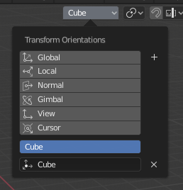
Transform Orientations panel.
The Transform Orientations panel, found in the header of the 3D View, can be used to manage transform orientations: selecting the active orientation, adding (“+” icon), deleting (“X” icon) and rename custom orientations.
The default name for these orientations comes from whatever you have selected. If an edge, it will be titled, “Edge”, if an object, it will take that object’s name, etc.
Create Orientation
To create a custom orientation, select the object or mesh element(s) and click the “+” button on the Transform Orientations panel.
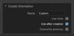
Create Orientation Adjust Last Operation panel.
Just after creating the orientation, the Create Orientation Adjust Last Operation panel gives a few options:
- Name
- Text field for naming the new orientation.
- Use View
- The new orientation will be aligned to the view space.
- Use after creation
- If checked it leaves the newly created orientation active.
- Overwrite previous
- If the new orientation is given an existing name, a suffix will be added to it to avoid overwriting the old one, unless Overwrite previous is checked, in which case it will be overwritten.
Align to Transform Orientation
Reference
| Mode: | Object and Edit Modes |
|---|---|
| Menu: |
Aligns (rotates) the selected objects so that their local orientation matches the active transform orientation in the Transform orientation panel or the Orientation selection in the Transform Adjust Last Operation panels.