Node Parts
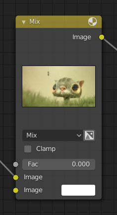
All nodes in Blender are based on a similar construction. This applies to any type of node. These parts include the Title, Sockets, Preview and more.
Title
The title shows the name/type of the node; it can be overridden by changing the node’s Label. On the left side of the title is the collapse toggle which can be used to collapse the node. This can also be done with H.
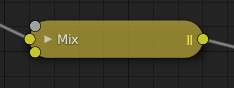
How a node appears when collapsed.
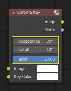
Sockets
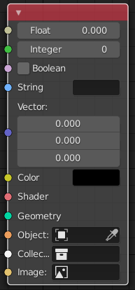
The sockets input and output values from the node. They appear as little colored circles on either side of the node. Unused sockets can be hidden with Ctrl-H. There are two kinds of sockets: inputs and outputs.
Each socket is color-coded depending on what type of data it handles.
- Float (gray)
Indicates numeric value’s information. It can either be a single numerical value or a so-called “value map”. (You can think of a value map as a gray-scale map where the different amount of bright/dark reflects the value for each point.) If a single value is used as an input for a “value map” socket, all points of the map are set to this same value. Common use: Alpha maps and value options for a node.
- Integer (lime green)
Used to pass an integer value (a number without a fractional component).
- Boolean (pink)
Used to pass a true or false value.
- String (light blue)
Used to pass a text value.
- Vector (dark blue)
Indicates vector, coordinate and normal information.
- Color (yellow)
Indicates that color information needs to be input or will be output from the node. Depending on the node tree type, the color has an alpha channel or not.
- Shader (bright green)
- Geometry (turquoise)
Used in Geometry Nodes.
- Object (orange)
Used to pass an object data-block.
- Collection (white)
Used to pass a collection data-block.
- Image (apricot)
Used to pass an image data-block.
Inputs
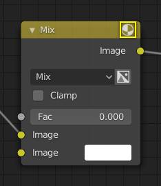
The inputs are located on bottom left side of the node, and provide the data the node needs to perform its function. Each input socket, except for the green shader input, when disconnected, has a default value which can be edited via a color, numeric, or vector interface input. In the screenshot of the node above, the second color option is set by a color interface input.
Some nodes have special sockets that can accept multiple inputs into a single socket. These sockets will have an ellipsis shape rather than a circle to indicate its special behavior.
Outputs
The outputs are located on the top right side of the node, and can be connected to the input of nodes further down the node tree.
Conversion
Some socket types can be converted to other socket types either implicitly or explicitly. Implicit conversion can happen automatically without the need of a conversion node.
For example, color and float sockets can both be placed into one another. Once a socket conversion is made data may be lost and cannot be retrieved later down the node tree. Implicit socket conversion can sometimes change the data units as well. When plugging a Value input node into an angle socket will default to use radians regardless of the scene Units. This happens because the value node has no unit while the angle input does.
Valid conversions:
Between color and vector – in this case the using individual color channels to store the vector.
Between color and float – the color data is converted to its gray scale equivalent.
Color/float/vector to Shader – implicitly converts to color and gives the result of using an emission node.
Explicit conversion requires the use of a conversion node for example the Shader To RGB node or the RGB to BW Node node. The Math Node node also contains some functions to convert between degrees and radians.