Bevel Vertices
Reference
- Mode
Edit Mode
- Menu
- Shortcut
Shift-Ctrl-B
- Menu
(edge bevel)
- Shortcut
Ctrl-B (edge bevel)
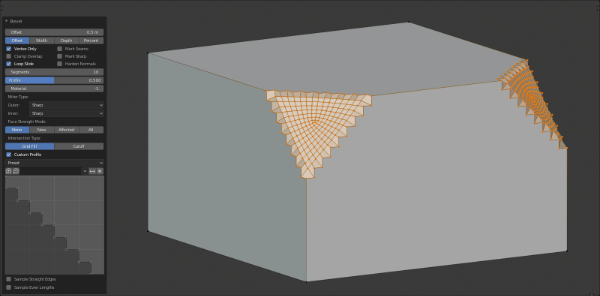
The Bevel tool rounds off edges or corners of a mesh at the point of the selected vertices. In “vertex only” mode, the Bevel Vertices tool works on selected vertices but the option to switch to Bevel Edges is available. By doing so, more vertices are added in order to smooth out profiles with a specified number of segments (see the options below for details about the bevel algorithm).
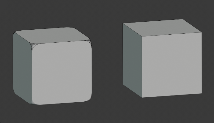
Cubes with and without bevel.
Note
With the Vertex Only option active, some of the other options available will not work. However, they will work with Bevel Edges.
Options
- Affect V
- Vertices
Only the areas near vertices are beveled, the edges remain unchanged.
- Edges
Bevel the edges, creating intersections at vertices.
- Offset A
You can change the bevel amount by moving the mouse towards and away from the object, like with transform tools. The exact meaning of the value depends on the Amount Type option (see below).
- Amount Type M
Selects how the Amount value controls the size of the bevel. According to the selection, the amount is:
- Offset
The relative distance from the new edge to the original.
- Width
The distance between the two new edges formed by the bevel (or the edges on either side of the bevel if there is more than one segment).
- Depth
The perpendicular distance from the original edge to the bevel face.
- Percent
The percentage of the length of adjacent edges that the new edges is slided along.
- Absolute
The exact distance along edges adjacent to the beveled edge. A difference from Offset is visible when the unbeveled edges attached to beveled edges meet at an angle besides a right angle.
For vertex-only bevels, the Offset and Depth types measure from the original vertex, and the Width type is measured from a new vertex to the center of the new face (as half the amount).
- Segments S
The number of segments in the bevel can be defined by scrolling the mouse Wheel to increase or decrease this value. The greater the number of segments, the smoother the bevel. Or press S to change the number with mouse movements, as well as numeric input.
Alternatively, you can manually enter a segment number value while using the tool, or in the Mesh Tool options panel after using the tool.
Bevel with four segments.
- Shape P
This is a number between 0 and 1 that controls the shape of the profile (side view of a beveled edge). The default value, 0.5, gives a circular arc (if the faces meet at right angles). Values less than that give a flatter profile, with 0.25 being exactly flat, and values less than that giving a concave bevel. Values more than 0.5 give a more convex profile. Similarly as Segments it can be set with mouse movements and numeric input after toggling P.
- Material Index
The Material number specifies which material should be assigned to the new faces created by the Bevel tool. With the default, -1, the material is inherited from the closest existing face (“closest” can be a bit ambiguous). Otherwise, the number is the slot index of the material to use for all newly created faces.
- Harden Normals H
When enabled, the per-vertex face normals of the bevel faces are adjusted to match the surrounding faces, and the normals of the surrounding faces are not affected. This will keep the surrounding faces flat (if they were before), with the bevel faces shading smoothly into them. For this effect to work, custom split normals need to be enabled, which requires Auto Smooth to be enabled (see Normals). As a convenience, that option will be enabled for you if it is not already when you enable Harden Normals here.
- Clamp Overlap C
Limits the width of each beveled edge so that vertices do not overlap with other geometry.
- Loop Slide
If there are un-beveled edges along with beveled edges into a vertex, the bevel tries to slide along those edges when possible. Turning the option off can lead to more even bevel widths.
- Face Strength Mode
Set Face Strength on the faces involved in the bevel, according to the specified mode. This can be used in conjunction with a Weight Normals Modifier (with the Face Influence option checked).
- None
Do not set face strength.
- New
Set the face strength of new faces along edges to Medium, and the face strength of new faces at vertices to Weak.
- Affected
In addition to those set for the New case, also set the faces adjacent to new faces to have strength Strong.
- All
In addition to those set for the Affected option, also set all the rest of the faces of the model to have strength Strong.
- Profile Type Z
- Superellipse
Creates a bevel with a uniform concave or convex curve.
- Custom
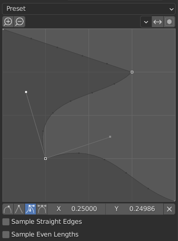
The custom profile widget.
This widget allows the creation of a user-defined profile with more complexity than with the single profile parameter. The modal tool allows toggling the custom profile, but the shape of the profile is only editable in the options panel after the operation is confirmed.
The profile starts at the bottom right of the widget and ends at the top left, as if it were between two edges intersecting at a right angle. Control points are created in the widget and then the path is sampled with the number of segments from the Bevel modifier.
- Presets
The Support Loops and Steps presets are built dynamically depending on the number of segments in the bevel. If the number of segments is changed, the preset will have to be re-applied.
- Sampling
Samples will first be added to each control point, then if there are enough samples, they will be divided evenly between the edges. The Sample Straight Edges option toggles whether the samples are added to edges with sharp control points on either side. If there aren’t enough samples to give each edge the same number of samples, they will just be added to the most curved edges. So it is recommended to use at least as many segments as there are control points.
Bevel with Custom Profile on.¶ 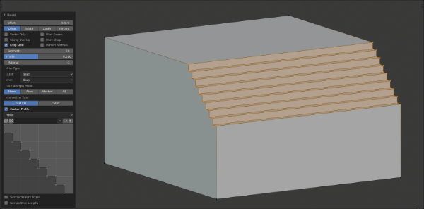
Edge Bevel.
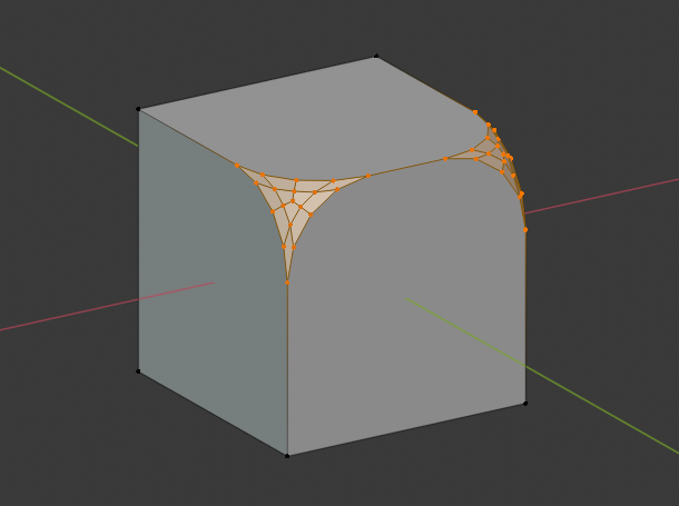
Vertex Bevel.
See also
The Bevel Modifier is a non-destructive alternative to the Bevel tool.