Bendy Bones
Reference
- Mode
All Modes
- Panel
Bendy Bones (B-Bones) are an easy way to replace long chains of many small rigid bones. A common use case for curved bones is to model spine columns or facial bones.
Technical Details
Blender treats the bone as a section of a Bézier curve passing through the bones’ joints. Each of the Segments will bend and roll to follow this invisible curve representing a tessellated point of the Bézier curve. The control points at each end of the curve are the endpoints of the bone. The shape of the B-Bones can be controlled using a series of properties or indirectly through the neighboring bones (i.e. first child and parent). The properties construct handles on either end of the bone to control the curvature.
When using the B-bone as a constraint target Data ID offers an option to follow the curvature.
Note
However, if the bone is used as a target rather than to deform geometry, only Armature and Copy Transforms constraints will use the full transformation including roll and scale.
Display
You can see these segments only if bones are visualized as B-bones.
When not visualized as B-Bones, bones are always shown as rigid sticks, even though the bone segments are still present and effective. This means that even in e.g. Octahedron visualization, if some bones in a chain have several segments, they will nonetheless smoothly deform their geometry.
Rest Pose
The initial shape of a B-Bone can be defined in Edit Mode as a rest pose of that bone. This is useful for curved facial features like curved eyebrows or mouths.
B-Bones have two sets of the Bendy Bone properties – one for Edit Mode (i.e. the Rest Pose/Base Rig) and another for Pose Mode – adding or multiplying together their values to get the final transforms.
Example

Bones with just one segment in Edit Mode. |
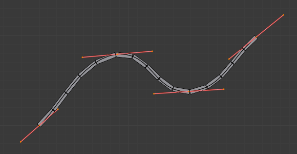
The Bézier curve superposed to the chain, with its handles placed at bones’ joints. |
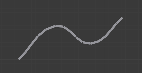
The same armature in Object Mode. |
In Fig. Bones with just one segment in Edit Mode. we connected three bones, each one made of five segments.
Look at Fig. The same armature in Object Mode., we can see how the bones’ segments smoothly “blend” into each other, even for roll.
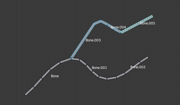
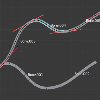
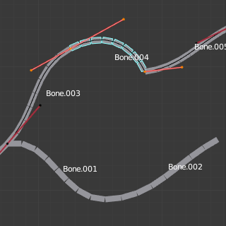
An armature in Pose Mode, B-Bone visualization: Bone.003 has one segment, Bone.004 has four, and Bone.005 has sixteen.
Options
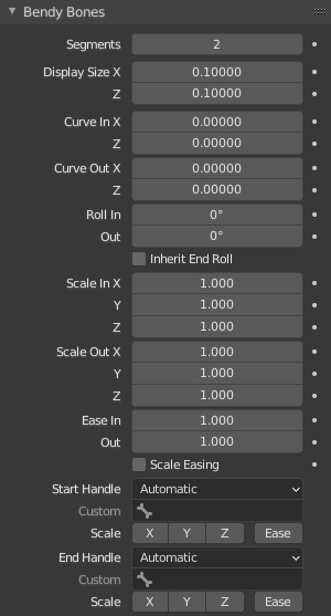
Bendy Bones panel.
- Segments
The number of segments, which the given bone is subdivided into. Segments are small, rigid linked child bones that interpolate between the root and the tip. The higher this setting, the smoother “bends” the bone, but the heavier the pose calculations.
- Display Size X, Z
Controls the visible thickness of the bone segments when the armature is rendered in the B-Bones mode.
- Curve In/Out X, Y, Z
Applies offsets to the curve handle positions on the plane perpendicular to the bone’s primary (Y) axis. As a result, the handle moves per axis (XZ) further from its original location, causing the curve to bend.
- Roll In, Out
The roll value (or twisting around the main Y axis of the bone) is interpolated per segment, between the start and end roll values. It is applied as a rotational offset on top of the rotation defined by the handle bones.
- Inherit End Roll
If enabled, the Roll Out value of the Start Handle bone (connected parent by default) will be implicitly added to the Roll In setting of the current bone.
- Scale In/Out X, Y, Z
Scaling factors that adjust the thickness of each segment for the X and Z axes, or introduce non-uniform spacing along the Y axis. Similar to Roll it is interpolated per segment.
Since all segments are still uniformly scaled in the Y direction to fit the actual length of the curve, only the ratio between Scale In Y and Scale Out Y actually matters.
- Ease In, Out
The Ease In/Out number fields, change the “length” of the “auto” Bézier handle to control the “root handle” and “tip handle” of the bone, respectively. These values are proportional to the default length, which of course automatically varies depending on bone length, angle with the reference handle, and so on.
Although easing is a scale-like value, the Edit Mode and Pose Mode versions of the values are added, so they get corresponding start values of 1 and 0 by default.
- Scale Easing
If enabled, the final easing values are implicitly multiplied by the corresponding Scale Y values.
Custom Handles
B-Bones can use custom bones as their reference bone handles, instead of only using the connected parent/child bones.
- Start/End Handle
Specifies the type of the handle from the following choices:
- Automatic
The connected parent (or first connected child) of the bone is chosen as the handle. Calculations are done according to the Absolute handle type below.
- Absolute
The Bézier handle is controlled by the position of the head (tail) of the handle bone relative to the head (tail) of the current bone. Note that for this to work, there must be a nonzero distance between these bones. If the handle is also a B-Bone, additional processing is applied to further smooth the transition, assuming that the bones in effect form a chain.
- Relative
The Bézier handle is controlled by the offset of the head (tail) of the handle bone from its rest pose. The use of this type is not recommended due to numerical stability issues near zero offset.
- Tangent
The Bézier handle is controlled by the orientation of the handle bone, independent of its location.
- Custom Handle
For types other than Automatic, a bone to use as handle has to be manually selected. Switching to a custom handle type without selecting a bone can be used to effectively disable the handle.
It is valid for two bones to refer to each other as handles – this correlation is applied in connected chains with Automatic handles.
- Scale X/Y/Z/Ease
If enabled, the final Scale and/or Ease values are multiplied by the corresponding local scale channels of the handle bone. This step is applied independently of Scale Easing and doesn’t interact with it, i.e. enabling Y and Scale Easing doesn’t replace the Ease toggle. These toggles are a more efficient replacement for up to eight trivial drivers passing segment scale data from the handle bones into the B-Bone option properties.
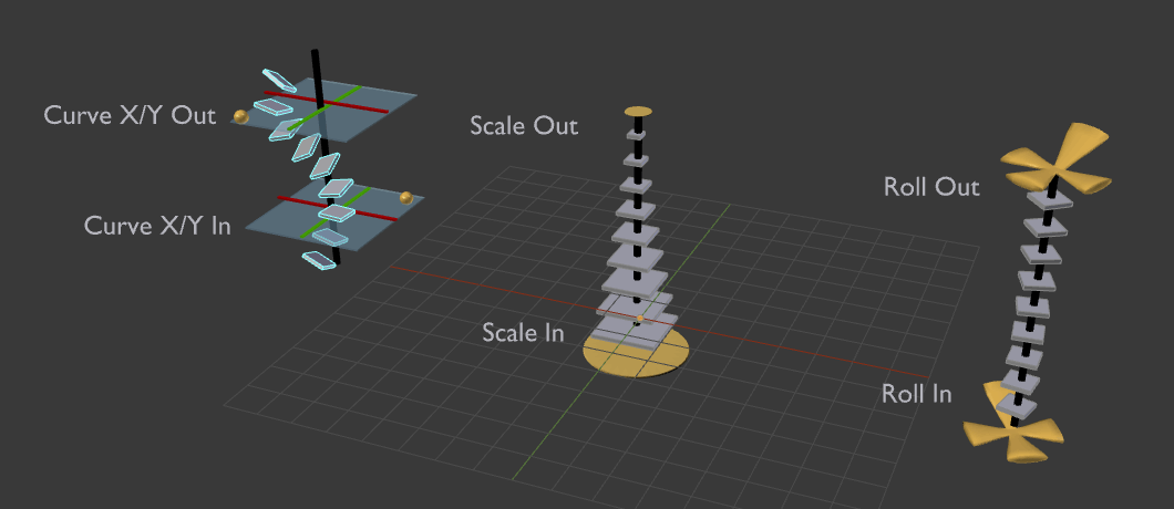
Visualization of the Bendy Bones properties.
From Left: 1) Curve X/Y offsets, 2) Scale In/Out, 3) Roll In/Out