Các Thao Tác (Operations)
This section will deal with explaining what the various Operations do. You can see a full list of available options in the table on the previous page (Before You Begin) for both Edit and Object modes.
Cursor:
This operation is concerned with placing the Cursor according to the various operators.
it can place the Cursor by Absolute coordinates, Delta Coordinates, Directional
Coordinates and either relative to its current position or an Active vertex, or Object.
Pivot Point:
This operation is concerned with placing the Pivot Point according to the various operators.
it can place the Cursor by Absolute coordinates, Delta Coordinates, Directional
Coordinates and either relative to its current position or an Active vertex, or Object.
Move:
This operation is concerned with Moving Geometry, or Objects according to the various operators.
geometry can be moved by Absolute coordinates, Delta Coordinates, Directional Coordinates.
in Edit mode, selected geometry is moved, in Object Mode selected Objects are moved.
Example 1: Move selected geometry 0.8 units at 34 degrees in front view, Set Operation to Move,
set Working Plane to Front(X-Z), set Distance to 0.8, set angle to 34, select geometry,
click Direction button.
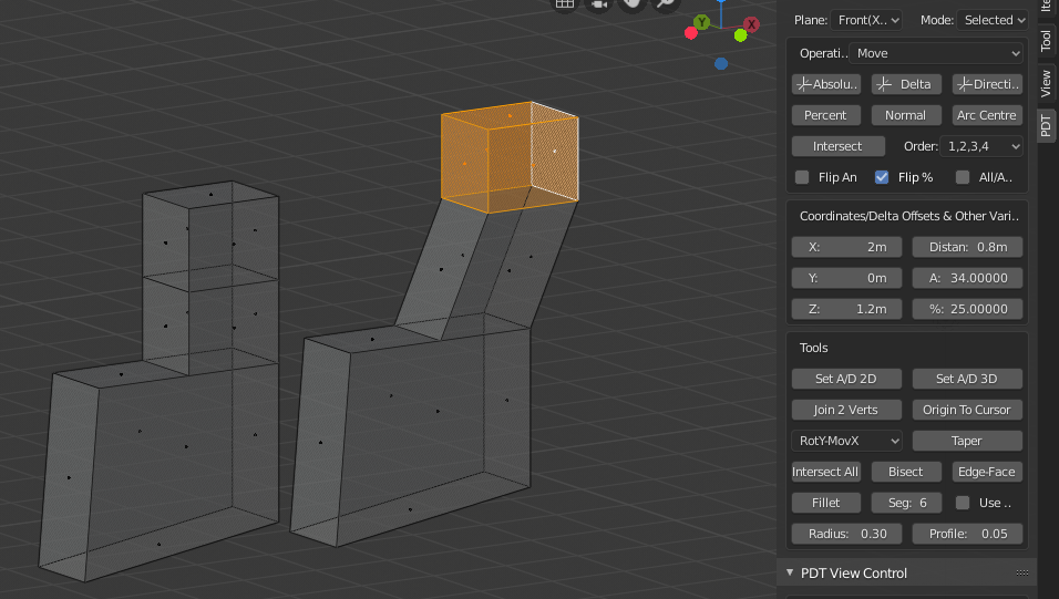
You can see the geometry Before and After the move.
New Vertex:
This operation is concerned with placing a New Vertex according to the various operators, the new vertex is set selected so it can then be manipulated.
Example 1: Place a New Vertex and the intersection of two edges, set Operation to New Vertex,
set Working Plane to Front(X-Z), select two edges, click Intersect button.
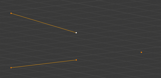
A new Vertex has been placed at the intersection of the two Edges.
Extrude Vertices:
This operation only Extrudes the vertices from selected geometry, so if you select a Face, and use this operation, only the vertices of the face will be extruded. this can also be used to "chase" a single vertex around a path, for example the edge of a complex bracket.
Example 1: Extrude the vertices of a face, set operation to Extrude Vertices,
select the face, set some delta offsets, click Delta button.
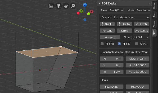
Only the Vertices from the Face have been extruded as edges.
Split Edges:
This operation will Split edges according to the operator you use. It will result in the face having one more vertex per operation, so a quad becomes a 5 sided Ngon. This initial split point is halfway along the chosen edge(s). If the system detects that you are going to split connecting edges of a face, which would ruin the topology, an error is given and the operation does not complete.
Example 1: Split the edge of a face at 25% of the way along it, set Operation to Split,
set Percent to 25, select one edge, click Percent button.
Example 2: Split two edges of an extruded prism and move the split 0.8 in X, 0.4 in Z,
set Operation to Split, set Working Plane to Front(X-Z), set X to 0.8 & Z to 0.4,
select two edges, click Delta button.
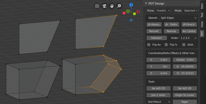
You can see Before and after of the two examples described above.
Duplicate Geometry:
This operation will duplicate geometry according to which operator is chosen.
Example 1: Duplicate selected geometry 3 units at 78 degrees in front view,
set Operation to Duplicate Geometry, set working plane to Front(X-Z),
set Distance to 3 & Angle to 78, click Direction button.
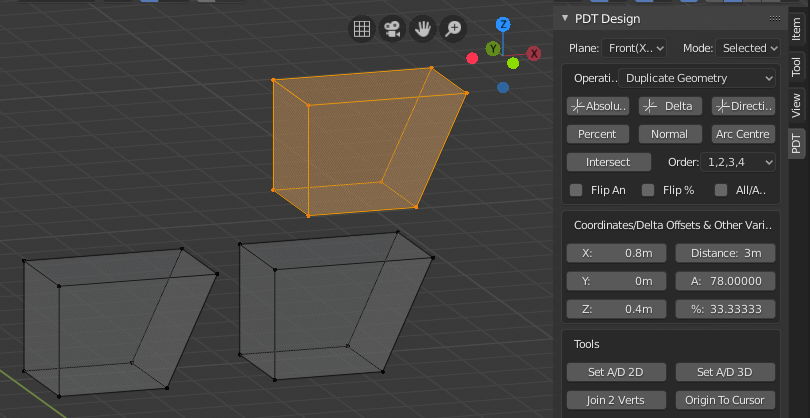
You can see Before and After states of a Duplication.
Extrude Geometry:
This operation will Extrude geometry, not just the vertices as with Extrude Vertex, but faces and edges as well.
Example 1: Extrude selected face 1 in X, 0.5 in Y and 0.6 in Z, set Operation to Extrude Geometry,
set Working Plane to Front(X-Z), set X, Y & Z to 1,0.5,0.6 respectively, click Delta button.
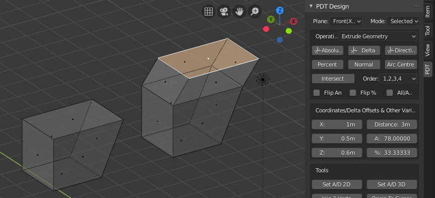
You can see the Top Face has been Extruded in all three axes as one operation.