Object Data
The curve properties can be set from the Object Data tab in the Properties Header (marked yellow in the image below).

Properties Editor Header.
Shape

Curves Shape panel.
- Dimensions
By default, new curves are set to be 3D, which means that control points can be placed anywhere in 3D space. Curves can also be set to 2D which constrain the control points to the curve’s local XY axis.
2D, 3D
- Resolution
The resolution property defines the number of points that are computed between every pair of control points. Curves can be made more or less smooth by increasing and decreasing the resolution respectively. The Preview U setting determines the resolution in the 3D View while the Render U setting determines the curve’s render resolution. If Render U is set to zero (0), then the Preview U setting is used for both the 3D View and render resolution.
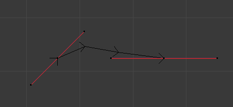
Curves with a resolution of 3.
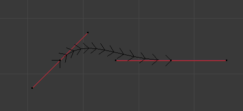
Curves with a resolution of 12.
- Twisting
A 3D curve has control points that are not located on the curve’s local XY plane. This gives the curve a twist which can affect the curve normals. You can alter how the twist of the curve is calculated by choosing from Minimum, Tangent and Z-Up options from the select menu.
Curves with a twist of Minimum.

Curves with a twist of Tangent.
- Fill
Fill determines the way a curve is displayed when it is beveled (see below for details on Beveling). When set to Half (the default) the curve is displayed as half a cylinder.
- Fill Deformed
- Fills the curve after applying all modification that might deform the curve (i.e. shape keys and modifiers).
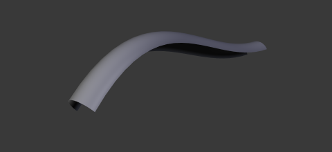
Curves with a fill of Half.
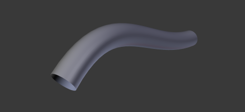
Curves with a fill of Full.
- Path/Curve-Deform
These options are utilized when using a curve as a path or when using the Curve Modifier. They control how objects use the curve.
- Radius
- Causes the deformed object to be scaled by the set curve radius.
- Stretch
- The Stretch curve option allows you to let the mesh object stretch, or squeeze, over the entire curve. To get the expected result, use this together with the Bounds Clamp option.
- Bounds Clamp
- When this option is enabled, the object and mesh offset along the deformation axis is ignored. This can be useful with the Stretch option or when using a negative axis.
Path Animation
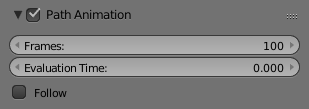
Path Animation panel.
The Path Animation settings can be used to determine how child objects move along a certain path.
- Frames
- The number of frames that are needed to traverse the path, defining the maximum value for the Evaluation Time setting.
- Evaluation Time
- Parametric position along the length of the curve that object following it should be at (the position is evaluated by dividing by the Path Length value). By default, it is linked to the global frame number, but could be keyframed to give more control over the path animation.
- Follow
- Make the curve path children rotate along the curvature of the path.
Note
Deprecated, but still available use. A more future-proof method is the Follow Path Constraint.
Example
This example shows you how setup a Path Animation.
- Add an object you want to animate and a path along which this object will move. In this example it’s the Monkey and the Bézier Circle.
- To parent the monkey to the Bézier circle, first select the monkey then the curve (so that the curve is the active object), press Ctrl-P and select Follow Path. It will automatically animate Evaluation Time and activate Follow option in the Path Animation panel.
- Select the monkey and Clear Origin Alt-O to reset its offset.
- You can change the orientation of the monkey by changing the Tracking Axes under Relations Extras (with the monkey selected).
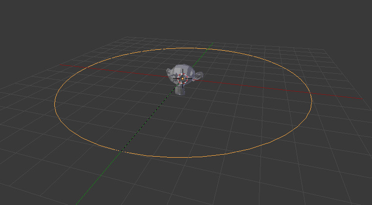
Monkey parented to the Bézier Circle. |
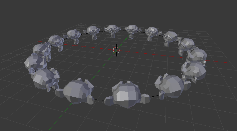
The final result. |
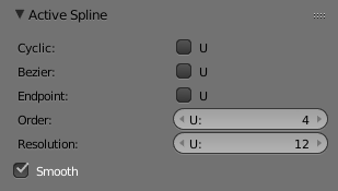
Active Spline

Curves Active Spline panel.
The Active Spline panel becomes available during Edit Mode.
- Cyclic
- Closes the curve.
- Resolution
- Alters the smoothness of each segment by changing the number of subdivisions.
- Interpolation
- Tilt
- Alters how the tilt of a segment is calculated.
- Radius
- Alters how the radius of a beveled curve is calculated. The effects are easier to see after Shrinking/Fattening a control point Alt-S.
- Smooth
- Smooths the normals of the curve.
NURBS Curves
NURBS Active Spline panel.
- Knots
One of the characteristics of a NURBS object is the knot vector. This is a sequence of numbers used to determine the influence of the control points on the curve. While you cannot edit the knot vectors directly, you can influence them through the Endpoint and Bézier options in the Active Spline panel. Note that, the Endpoint and Bézier settings only apply to open NURBS curves.
- Cyclic
Makes the NURBS curve cyclic.
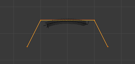
Default NURBS curve.
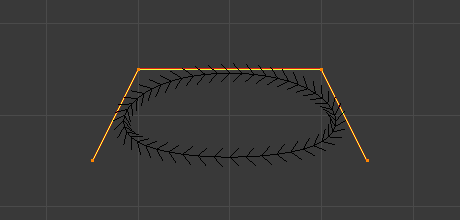
A NURBS curve with Cyclic applied.
- Bézier
- Makes the NURBS curve act like a Bézier curve. The NURBS control points act like Free handles of Bézier curve. Depending on the Order, 3 or 4 control points form one curve segment. Cyclic and Endpoint must be disabled for this option to work.
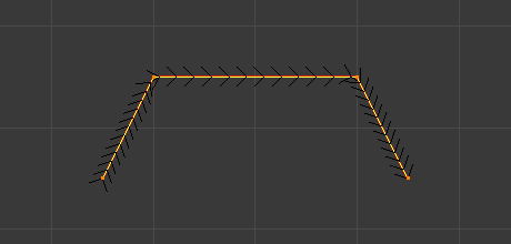
- Endpoint
Makes the curve contact the end control points. Cyclic must be disabled for this option to work.
Default NURBS curve.
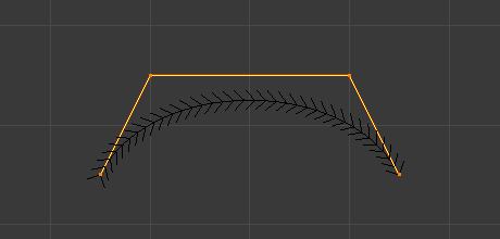
A NURBS curve with Endpoint enabled.
- Order
The order of the NURBS curve determines the area of influence of the control points over the curve. Higher order values means that a single control point has a greater influence over a greater relative proportion of the curve. The valid range of Order values is 2-6 depending on the number of control points present in the curve.
NURBS curves with orders of 4.
NURBS curves with orders of 2.