Face Tools
Reference
- Mode
Edit Mode
- Menu
- Hotkey
Ctrl-F
These are tools that manipulate faces.
Fill
Reference
- Mode
Edit Mode
- Menu
- Hotkey
Alt-F
The Fill option will create triangular faces from any group of selected edges or vertices, as long as they form one or more complete perimeters.
- Beauty
Arrange the new triangles nicely.
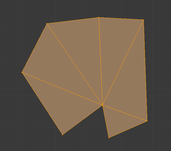
Filled using fill.
Note, unlike creating n-gons, Fill supports holes.
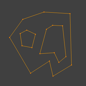
A closed perimeter of edges with holes.¶ |
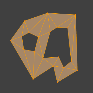
Filled using fill.¶ |
Beautify Faces
Reference
- Mode
Edit Mode
- Menu
Beautify Faces works only on selected existing faces. It rearrange selected triangles to obtain more “balanced” ones (i.e. less long thin triangles).
- Max Angle
An angle delimiter option to limit edge rotation to flat surfaces.

Text converted to a mesh.¶ |

Result of Beautify Faces.¶ |
Grid Fill
Reference
- Mode
Edit Mode
- Menu
Grid Fill uses a pair of connected edge loops or a single, closed edge loop to fill in a grid that follows the surrounding geometry.
The best predictable result can be achieved if you select two opposite edge loops with an equal number of vertices. When a single, closed edge loop is selected, the Span/Offset options allows you to adjust the way two opposite edge loops are detected from one closed edge loop.
- Span
Specifies the number of columns in the grid.
- Offset
Defines the vertex that is considered to be the corner of the grid, by default, it’s the active vertex. The Offset allows you to rotate the grid lines.
- Simple Blending
Use a simple interpolation algorithm to generate grid vertices from boundary loops, which doesn’t attempt to maintain the shape, useful for flat surfaces or times when keeping the shape gives odd results.
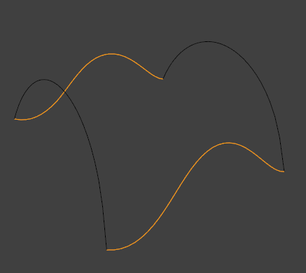
Input.¶ |
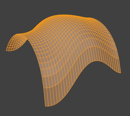
Grid Fill result.¶ |
Solidify
Reference
- Mode
Edit Mode
- Menu
This takes a selection of faces and solidifies them by extruding them uniformly to give volume to a non-manifold surface. This is also available as a Modifier. After using the tool, you can set the offset distance in the Adjust Last Operation panel.
- Thickness
Amount to offset the newly created surface. Positive values offset the surface inward relative to the normals direction. Negative values offset outward.
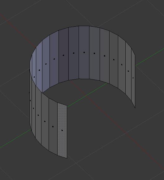
Mesh before solidify operation.¶ |
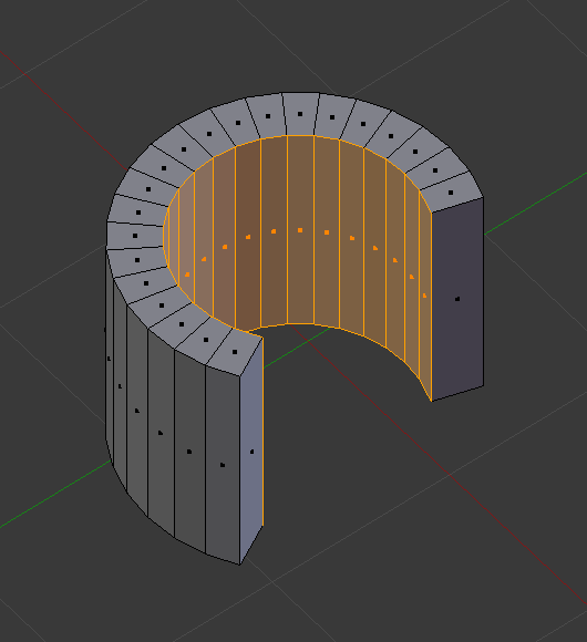
Solidify with a positive thickness.¶ |
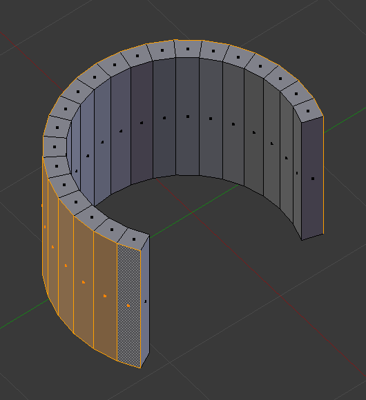
Solidify with a negative thickness.¶ |
Intersect
Intersect (Knife)
Reference
- Mode
Edit Mode
- Menu
The Intersect tool lets you cut intersections into geometry. It is a bit like Boolean Tool, but, does not calculate interior/exterior. Faces are split along the intersections, leaving new edges selected.
- Source
- Selected/Unselected
Operate between the selected and unselected geometry.
- Self Intersect
Operate on the overlapping geometry of the mesh.
- Separate Mode
- All
Splits the geometry at the new edge.
- Cut
Keep each side of the intersection separate without splitting the faces in half.
- Merge
Merge all the geometry from the intersection.
- Merge Threshold
See Intersect (Boolean).
Intersect (Boolean)
Reference
- Mode
Edit Mode
- Menu
Performs boolean operations with the selection on the unselected geometry. While the Boolean Modifier is useful for non-destructive edits, access to booleans with a tool in Edit Mode can be useful to quickly perform edits.
- Boolean
Difference, Union, Intersect
- Swap
Changes the order of the operation.
- Merge Threshold
Tolerance for close faces to be considered touching, It may be useful to increase this when some intersections aren’t detected that should be and when extra geometry is being created because edges aren’t detected as overlapping.
Warning
A threshold approaching size of faces may cause very slow calculation, in general keep this value small.
Wireframe
Reference
- Mode
Edit Mode
- Menu
The Wireframe tool makes a wireframe from faces by turning edges into wireframe tubes, similar to the Wireframe Modifier.
Poke Faces
Reference
- Mode
Edit Mode
- Menu
Splits each selected faces into a triangle fan, creating a new center vertex and triangles between the original face edges and new center vertex. The Offset can be used to make spikes or depressions.
- Poke Offset
Offset the new center vertex along the face normal.
- Offset Relative
Multiply the Offset by the average length from the center to the face vertices.
- Poke Center
Computes the center of a face.
- Weighted Mean
Using the mean average weighted by edge length.
- Mean
Using the mean average.
- Bounds
Uses center of bounding box.
Triangulate Faces
Reference
- Mode
Edit Mode
- Menu
- Hotkey
Ctrl-T
This tool converts each of the selected faces (whether it be quads or n-gons) to triangular faces. See the Triangulate Modifier.
Triangles to Quads
Reference
- Mode
Edit Mode
- Menu
- Hotkey
Alt-J
This tool converts the selected triangles into quads by taking adjacent triangles and removing the shared edge to create a quad, based on a threshold. This tool can be applied on a selection of multiple triangles.
This means you can select the entire mesh and convert triangles that already form square shapes – to be converted into quads, without having to concern yourself with individual faces.
Alternatively you can force this operation selecting a pairs of faces (see hint below for other ways of joining).
To create a quad, this tool needs at least two adjacent triangles. If you have an even number of selected triangles, it is also possible not to obtain only quads. In fact, this tool tries to create most even rectangular quads from the given triangles, which means some triangles could remain.
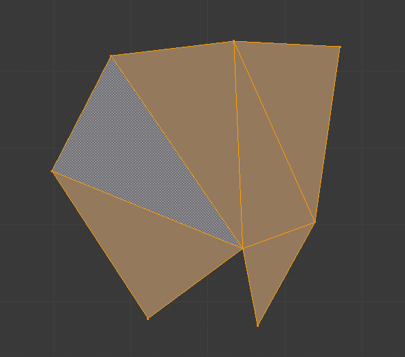
Before converting tris to quads.¶ |
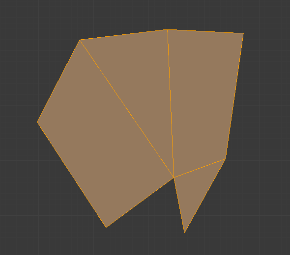
After converting tris to quads.¶ |
All the menu entries and hotkeys use the settings defined in the Operator panel:
- Max Angle
This value, between (0 to 180), controls the threshold for this tool to work on adjacent triangles. With a threshold of 0.0, it will only join adjacent triangles that form a perfect rectangle (i.e. right-angled triangles sharing their hypotenuses). Larger values are required for triangles with a shared edge that is small, relative to the size of the other edges of the triangles.
- Compare UVs
When enabled, it will prevent the union of triangles that are not also adjacent in the active UV map.
- Compare Vertex Color
When enabled, it will prevent the union of triangles that have no matching vertex color.
- Compare Sharp
When enabled, it will prevent the union of triangles that share an edge marked as sharp.
- Compare Materials
When enabled, it will prevent the union of triangles that do not have the same material assigned.
Hint
When isolated groups of faces are selected, they can be combined with Create Face or Dissolve Faces; this is not limited to quads.
Weld Edges into Faces
Reference
- Mode
Edit Mode
- Menu
A tool to split selected faces by loose wire edges. This can be used in a similar way to the Knife tool, but the edges are manually setup first.
Rotate Edges
Reference
- Mode
Edit Mode
- Menu
This tool functions the same edge rotation in edge mode. It works on the shared edge between two faces and rotates that edge if the edge was selected.
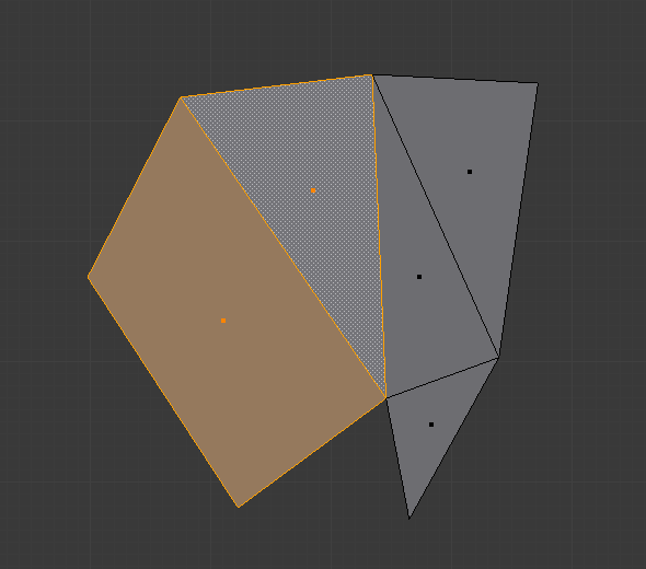
Two adjacent faces selected.¶ |
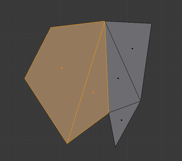
Selected edge rotated.¶ |
See Rotate Edge for more information.
Rotate & Reverse
- Rotate/Reverse UVs
- Rotate Colors
Rotates the Vertex Colors inside faces either clockwise or counterclockwise.
- Reverse Colors
Flips the direction of Vertex Colors inside the selected faces.
Normals
See Editing Normals for more information.