Extrude
Extrusion tools duplicate vertices, while keeping the new geometry connected with the original vertices. Vertices are turned into edges and edges will form faces.
Single vertex extruded. |
Single edge extruded. |
This tool is of paramount importance for creating new geometry. It allows you to create parallelepipeds from rectangles and cylinders from circles, as well as easily creating such things as tree limbs.
The axis on which vertices and edges are extruded along can be set interactively. Faces are extruded by default along their averaged normal. The extrusion can be limited to a single axis by specifying an axis; see Axis Locking.
The extrude tools differentiate in how the new geometry is connected in itself.
- Flip Normals
- Reverses the normal's direction for any resulting geometry.
Extrude Region
Reference
| Mode: | Edit Mode |
|---|---|
| Panel: | |
| Menu: | |
| Hotkey: | E |
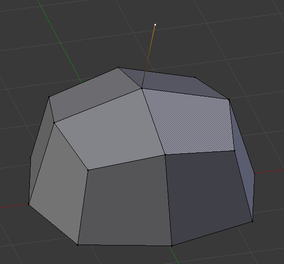
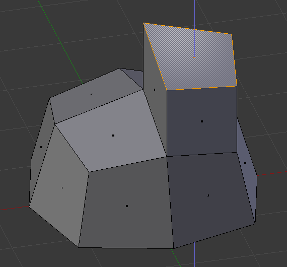
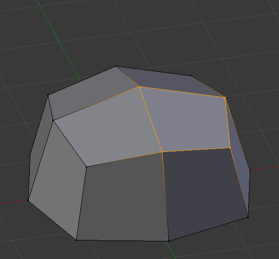
Only the border loop gets extruded. The inner region of the selection gets moved unchanged with the extrusion.
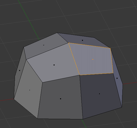
Selected face. |
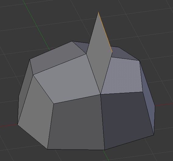
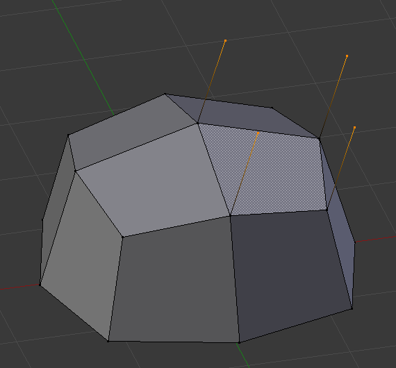
During extrude. |
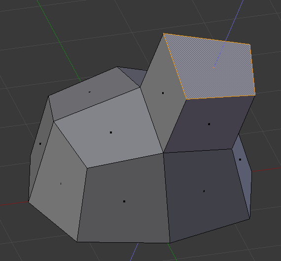
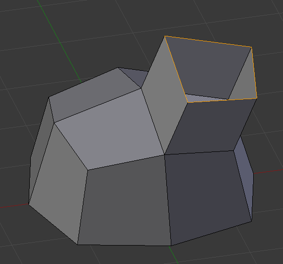
Set to Z axis. |
Details
Although the process is quite intuitive, the principles behind Extrude are fairly elaborate as discussed below:
- First, the algorithm determines the outside edge loop of the extrude; that is, which among the selected edges will be changed into faces. By default (see below), the algorithm considers edges belonging to two or more selected faces as internal, and hence not part of the loop.
- The edges in the edge loop are then changed into faces.
- If the edges in the edge loop belong to only one face in the complete mesh, then all of the selected faces are duplicated and linked to the newly created faces. For example, rectangles will result in parallelepipeds during this stage.
- In other cases, the selected faces are linked to the newly created faces but not duplicated. This prevents undesired faces from being retained "inside" the resulting mesh. This distinction is extremely important since it ensures the construction of consistently coherent, closed volumes at all times when using Extrude.
- When extruding completely closed volumes (like e.g. a cube with all its six faces), extrusion results merely in a duplication, as the volume is duplicated, without any link to the original one.
- Edges not belonging to selected faces, which form an "open" edge loop, are duplicated and a new face is created between the new edge and the original one.
- Single selected vertices which do not belong to selected edges are duplicated and a new edge is created between the two.
Extrude Individual
Reference
| Mode: | Edit Mode |
|---|---|
| Panel: | |
| Menu: | |
| Hotkey: | Alt-E |
Extrude Individual allows you to extrude a selection of multiple faces as individuals, instead of as a region. The faces are extruded along their own normals, rather than their average. This has several consequences: first, "internal" edges (i.e. edges between two selected faces) are no longer deleted (the original faces are).
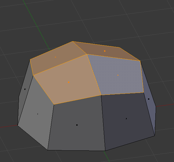
Selection of multiple faces. |
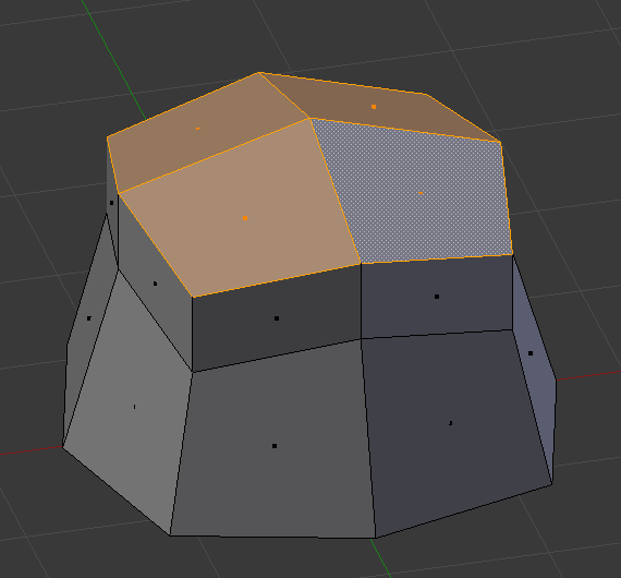
Extruded using extrude region. |
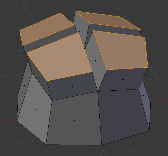
Extruded using Extrude Individual. |
Extrude Edges and Vertices Only
Reference
| Mode: | Edit Mode, Vertex and Edge |
|---|---|
| Panel: | |
| Menu: | |
| Hotkey: | Alt-E |
If vertices are selected while doing an extrude, but they do not form an edge or face, they will extrude as expected, forming a non-manifold edge. Similarly, if edges are selected that do not form a face, they will extrude to form a face.
When a selection of vertices forms an edge or face, it will extrude as if the edge was selected. Likewise for edges that form a face.
To force a vertex or edge selection to extrude as a vertex or edge, respectively, use Alt-E to access the Extrude Edges Only and Vertices Only.
Vertex selected. |
Vertices Only extrude. |

Edge selected. |
Edge Only extrude. |
Extrude Repeat Mesh
Reference
| Mode: | Edit Mode |
|---|---|
| Menu: |
This tool has to be called from Operator Search. If the selection is not manifold it's extruded the specified number of times, else it behaves similar to the Array Modifier. The extrusion is aligned along the Z axis of the view.
- Offset
- Distance between the instances.
- Steps
- Number of instances.