選択
要素を選択する方法は数多くありますが、どの選択ツールが利用できるかは、現在使用中の メッシュ選択モード によって変わります。最初にこれらのモードについて説明し、その後、基本的な選択ツールについて説明します。
選択モード
選択モードヘッダーボタン
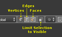
Editモード選択ボタン
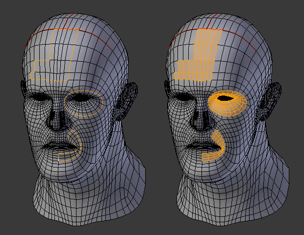
Editモード には、三つの選択モードがあります。ヘッダーにある三つのボタンのうち一つを選択することで、別のモードに入ることができます。
- 頂点 (Vertices)
このモードでは、頂点は点として表示されます。
選択中の頂点はオレンジ色で、選択されていない頂点は黒色で、有効(アクティブ)な頂点や、最後に選択された頂点は白色で表示されます。
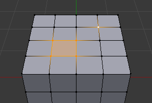
- 辺 (Edges)
このモードでは、頂点は表示されません。
その代わりに、選択中の辺がオレンジ色で、選択されていない辺は黒色で、有効(アクティブ)な辺や最後に選択された辺は白色で表示されます。
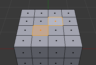
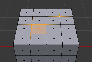
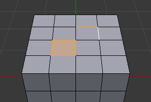
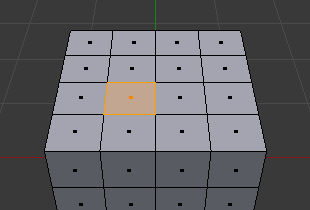
- 面 (Faces)
このモードでは、選択中の面とその中心に選択点が表示されます。
選択中の面とそれらの選択点がオレンジ色で、選択させていない面が黒色で、有効(アクティブ)な面や最後に選択された面は白色で表示されます。
これらのボタンを使用中に、モディファイアーキー(modifier keys)を使うことができます。Switching Select Mode を参照してください。
これら三つのメッシュ選択モードでは、ほとんど全てのツールを利用できます。従って、回転、スケール、押し出しなどが全てのモードで可能です。もちろん、(他の位置にピボットポイントを設定していなければ) 単一の 頂点を回転させたりスケールさせることに意味はありません。よって、モードによってはツールの有用性が変わります。
モードによる違いの例について図 選択モード を参照ください。
選択モードの切り替え
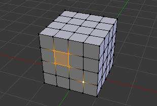
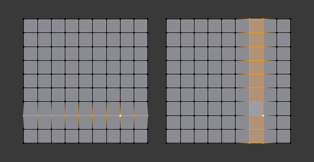
頂点から辺へ、辺から面へといったように"昇順(ascendant way)" (つまり、シンプルなものからもっと複雑なものへ)にモード切替を行う場合で、切り替え後のモードで完全な要素になる場合には、選択済みのパーツは選択状態が維持されます。
例えば、ある面の全ての四辺が選択されており、辺モードから面モードに切り替えた場合、面の選択が維持されます。切り替え後のモードで完全なセットを形成できない選択部分については、全て選択が解除されます。
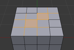
辺モードでの最初の選択状態¶ |
面モードへの切り替え¶ |
従って、"降順(descendant way)" (つまり、複雑なものからシンプルなものへ)に切り替えた場合、面のように"高次(high-level)"の要素を定義する全ての要素(例えば、四つの頂点や四角形の辺)は、選択された状態となります。
Selection Tools
Checker Deselect
リファレンス
- モード
Editモード
- メニュー
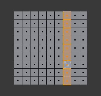
This tool applies an alternating selected/deselected checker pattern. This only works if you already have more than one mesh element selected.
Changes the current selection so that only every Nth elements (vertices, edges or faces, depending on the active selection mode) will remain selected, starting from the active one.
In case of islands of selected elements, this tool will affect only the island of the active element (if there is one), or the island of the first element in the order of internal storage (if there is no active element).
- Deselected
The number of deselected elements in each pattern repetition.
- Selected
The number of selected elements in each pattern repetition.
- Offset
Offset from the starting point.
Select All by Trait
- Non Manifold
Selects the non-manifold geometry of a mesh. This entry is available when editing a mesh, in Vertex and Edge selection modes only.
- Extend
Lets you extend the current selection.
- Wire
Selects all the edges that do not belong to any face.
- Boundaries
Selects edges in boundaries and holes.
- Multiple Faces
Selects edges that belong to three or more faces.
- Non Contiguous
Selects edges that belong to exactly two faces with opposite normals.
- 頂点 (Vertices)
Selects vertices that belong to wire and multiple face edges, isolated vertices, and vertices that belong to non-adjoining faces.
- Loose Geometry
This selection depends on the currently selected Selection Modes; In vertex and edge selection mode it selects all vertices or edges that do not form part of a face. In face selection mode it selects all faces that do not share edges with other faces.
- Interior Faces
Selects faces where all edges have more than two faces.
- Faces by Sides
Selects all faces that have a specified number of edges.
- Ungrouped Vertices
Selects all vertices which are not part of a vertex group.
Select Linked
リファレンス
- モード
Editモード
- メニュー
- ショートカットキー
Ctrl-L
Select geometry connected to already selected elements. This is often useful when a mesh has disconnected, overlapping parts, where isolating it any other way would be tedious.
To give more control, you can also enable delimiters in the Adjust Last Operation panel, so the selection is constrained by seams, sharp edges, materials or UV islands.
With Pick Linked you can also select connected geometry directly under the cursor, using the L shortcut to select or Shift-L to deselect linked.
This works differently in that it uses the geometry under the cursor instead of the existing selection.
Select Similar
リファレンス
- モード
Editモード
- メニュー
- ショートカットキー
Shift-G
Select geometry that has similar certain properties to the ones selected, based on a threshold that can be set in tool properties after activating the tool. Tool options change depending on the selection mode:
- Vertex Selection Mode:
- Normal
Selects all vertices that have normals pointing in similar directions to those currently selected.
- Amount of Adjacent Faces
Selects all vertices that have the same number of faces connected to them.
- Vertex Groups
Selects all vertices in the same vertex group.
- Amount of Connecting Edges
Selects all vertices that have the same number of edges connected to them.
- Face Regions
Select matching features on a mesh that has multiple similar areas based on the topology.
- Edge Selection Mode:
- Length
Selects all edges that have a similar length as those already selected.
- Direction
Selects all edges that have a similar direction (angle) as those already selected.
- Amount of Faces Around an Edge
Selects all edges that belong to the same number of faces.
- Face Angles
Selects all edges that are between two faces forming a similar angle, as with those already selected.
- Crease
Selects all edges that have a similar Crease value as those already selected.
- Bevel
Selects all edges that have the same Bevel Weight as those already selected.
- Seam
Selects all edges that have the same Seam state as those already selected. Seam is a true/false setting used in UV texturing.
- Sharpness
Selects all edges that have the same Sharp state as those already selected. Sharp is a true/false setting (a flag) used by the Edge Split Modifier.
- Face Selection Mode:
- Material
Selects all faces that use the same material as those already selected.
- Image
Selects all faces that use the same UV texture as those already selected (see UV texturing pages).
- Area
Selects all faces that have a similar area as those already selected.
- Polygon Sides
Selects all faces that have the same number of edges.
- Perimeter
Selects all faces that have a similar perimeter (added values of its edge lengths).
- Normal
Selects all faces that have a similar normal as those selected. This is a way to select faces that have the same orientation (angle).
- Co-planar
Selects all faces that are (nearly) in the same plane as those selected.
Edge Loops
リファレンス
- モード
Edit Mode (Vertex or Edge select mode)
- メニュー
- ショートカットキー
Alt-LMB, or Shift-Alt-LMB for modifying existing selection.
Holding Alt while selecting an edge selects a loop of edges that are connected in a line end-to-end, passing through the edge under the mouse pointer. Holding Shift-Alt while clicking adds to the current selection.
Edge loops can also be selected based on an existing edge selection, using either .
注釈
Vertex mode
In Vertex select mode, you can also select edge loops, by using the same hotkeys, and clicking on the edges (not on the vertices).
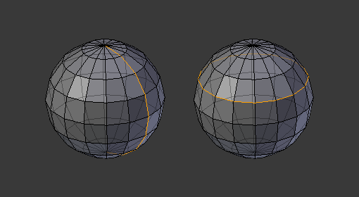
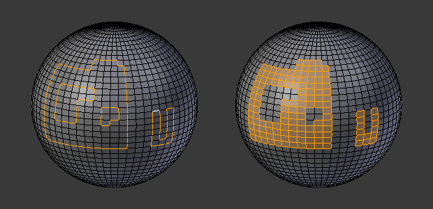
Longitudinal and latitudinal edge loops.
The left sphere shows an edge that was selected longitudinally. Notice how the loop is open. This is because the algorithm hit the vertices at the poles and is terminated because the vertices at the pole connect to more than four edges. However, the right sphere shows an edge that was selected latitudinally and has formed a closed loop. This is because the algorithm hit the first edge that it started with.
Edge Loops (All Boundaries)
All boundary edges can be selected by performing a second loop select action on a boundary edge.
This can be useful for selecting boundaries for meshes that include triangles and n-gons, where loop select would not otherwise select the full boundary.
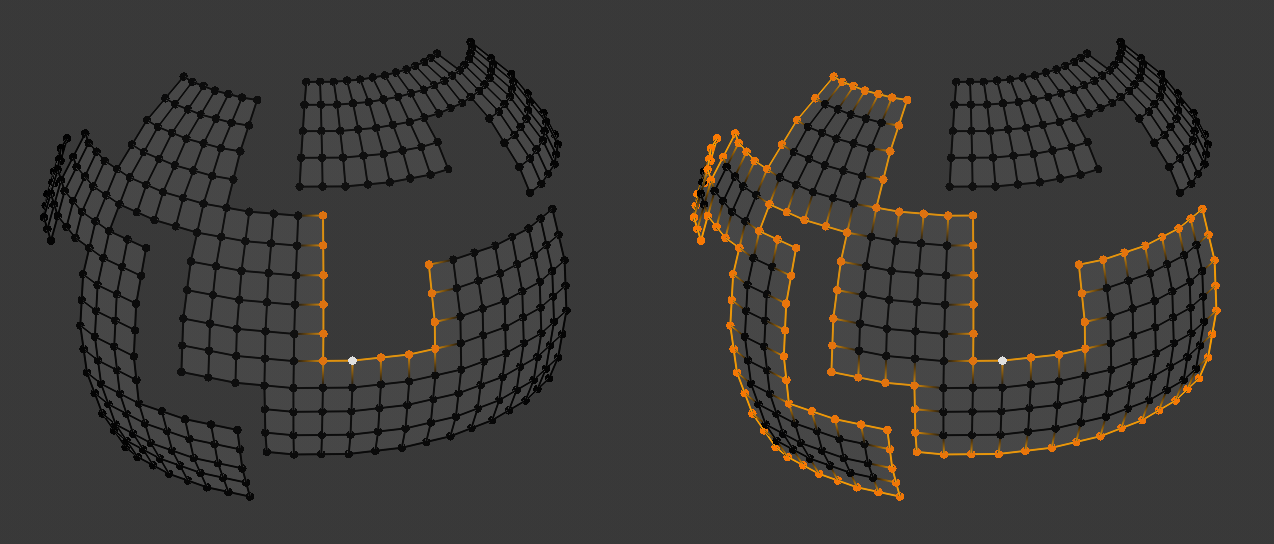
The second loop select action is shown on the right.
Face Loops
リファレンス
- モード
Edit Mode (Face or Vertex select modes)
- ショートカットキー
Alt-LMB or Shift-Alt-LMB for modifying existing selection.
In face select mode, holding Alt while selecting an edge selects a loop of faces that are connected in a line end-to-end, along their opposite edges.
In vertex select mode, the same can be accomplished by using Ctrl-Alt to select an edge, which selects the face loop implicitly.
Face loop selection.
This face loop was selected by clicking with Alt-LMB on an edge, in face select mode. The loop extends perpendicular from the edge that was selected.
Alt versus Ctrl-Alt in vertex select mode.
A face loop can also be selected in Vertex select mode. Technically Ctrl-Alt-LMB will select an Edge Ring, however, in Vertex select mode, selecting an Edge Ring implicitly selects a Face Loop since selecting opposite edges of a face implicitly selects the entire face.
Edge Ring
リファレンス
- モード
Editモード
- メニュー
- ショートカットキー
Ctrl-Alt-LMB
In Edge select mode, holding Ctrl-Alt while selecting an edge (or two vertices) selects a sequence of edges that are not connected, but on opposite sides to each other continuing along a face loop.
As with edge loops, you can also select edge rings based on current selection, using either .
注釈
Vertex mode
In Vertex select mode, you can use the same hotkeys when clicking on the edges (not on the vertices), but this will directly select the corresponding face loop...
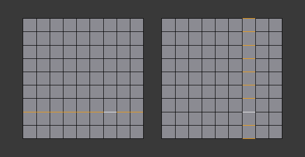
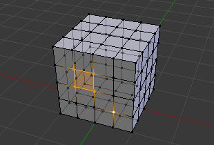
A selected edge loop, and a selected edge ring.
In Fig. A selected edge loop, and a selected edge ring. the same edge was clicked on, but two different "groups of edges" were selected, based on the different tools. One is based on edges during computation and the other is based on faces.
注釈
Convert Selection to Whole Faces
If the edge ring selection happened in Edge Select Mode, switching to Face Select Mode will erase the selection.
This is because none of those faces had all its (four) edges selected, just two of them.
Instead of selecting the missing edges manually or by using Shift-Alt- twice, it is easier to first switch to Vertex Select Mode, which will kind of "flood" the selection. A subsequent switch to Face Select Mode will then properly select the faces.
Shortest Path
リファレンス
- モード
Editモード
- メニュー
- ショートカットキー
Ctrl-LMB
Select a face or vertex path with Ctrl-LMB.
Selects all geometry along the shortest path from the active vertex/edge/face to the one which was selected.
- Edge Tag (in Edge select mode only)
This select button indicates what should be done when selecting a vertex path with Ctrl-LMB:
- Select
Just selects all the edges in the path.
- Tag Seam
Marks all edges in the path as seams for UV unwrapping.
- Tag Sharp
Marks all edges in the path as sharp for the Edge Split Modifier.
- Tag Crease
Marks all edges in the path as creases for the Subdivision Surface Modifier, with weight 1.0.
- Tag Bevel
Gives bevel weight 1.0 (for the Bevel Modifier) to all edges in the path.
- Tag Freestyle Edge Mark
Marks all edges in the path Freestyle feature edges.
- Face Stepping
Supports diagonal paths for vertices and faces, and selects edge rings with edges.
- Topological Distance
Only takes into account the number of edges of the path and not the length of the edges to calculate the distances.
- Fill Region Shift-Ctrl-LMB
Selects all elements in the shortest paths from the active selection to the clicked area.
- Checker Deselect Options
Allows to quickly select alternate elements in a path. See also Checker Deselect tool.
- Deselected
The number of deselected elements in the repetitive sequence.
- Selected
The number of selected elements in the repetitive sequence.
- Offset
Offset from the starting point.
Loop Inner-Region
リファレンス
- モード
Edit Mode (Edge select mode)
- メニュー
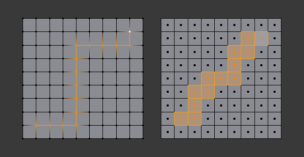
Select Loop Inner-Region selects all faces that are inside a closed loop of edges. While it is possible to use this operator in Vertex and Face selection modes, results may be unexpected. Note that if the selected loop of edges is not closed, then all connected edges on the mesh will be considered inside the loop.
Loop to Region.
This tool handles multiple loops fine, as you can see.
This tool handles "holes" just fine as well.
Boundary Loop
リファレンス
- モード
Edit Mode (Edge select mode)
- メニュー
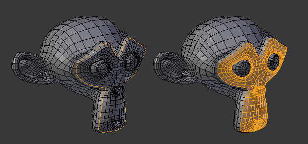
Select Boundary Loop does the opposite of Select Loop Inner-Region, based on all regions currently selected, it selects only the edges at the border(contour) of these islands. It can operate in any select mode, but when in Face mode it will switch to Edge select mode after running.
All this is much more simple to illustrate with examples:
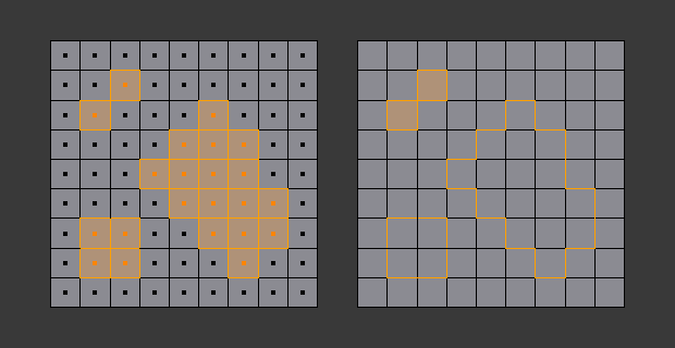
Select Boundary Loop does the opposite and forces into Edge Select Mode.
Known Issues
Dense Meshes
Selecting dense meshes with X-Ray disabled, has a limitation where dense meshes may not have all the elements selected.
When selecting regions with Box, Circle and Lasso select, vertices may overlap each other causing some vertices not to be selected.
This is a limitation with the current selection method, you may workaround this by zooming in or enabling X-Ray.
N-Gons in Face Select Mode
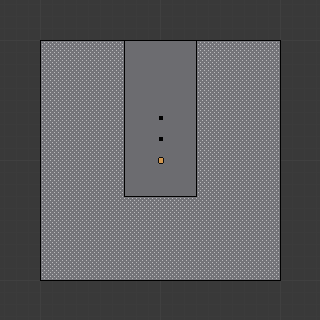
N-gon face having its center dot inside another face.
As already noted, in X-Ray and Wireframe mode faces are marked with a dot in the middle. With n-gons that can lead in certain cases to a confusing display. The example shows the center dot of the U-shaped n-gon being inside of the oblong face inside the "U". It is not easy to say which dot belongs to which face (the orange dot in the image is the object origin).