構造
メッシュでは、全てが3つの基本的な構造、すなわち 頂点(Vertex) 、辺(Edge)、 面(Face) から成ります。

メッシュ構造の例
頂点 (Vertex)
メッシュの最も基本的なパーツが頂点で、3D空間における単一点、位置を示します。Editモードにおける3D Viewport内で、頂点は小さなドットで表現されています。オブジェクトの頂点は、座標の配列として格納されます。
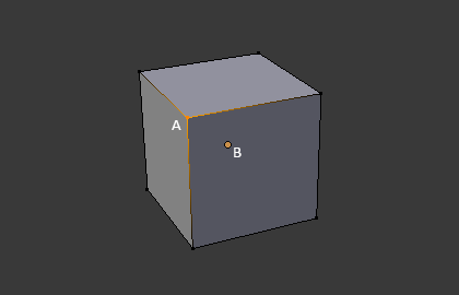
辺 (Edge)
辺は必ず2つの頂点を真っ直ぐな線で繋いでいます。辺は、メッシュをワイヤーフレームで見た時に「ワイヤー」として見えるものです。レンダー画像では通常、見えません。面を作るために使われます。
面 (Face)
面はオブジェクトの実際の表面を作るために使われます。メッシュのレンダリングの結果として見えるのはこの面です。その領域が面を持っていない場合は、レンダリング結果では透明もしくは存在しない物として出力されます。
1つの面は3つ(三角形、triangles)、4つ(四角形、quadrangles)、それ以上の数(nゴン、n-gons)の頂点の間にあり、辺で囲まれた領域として定義されます。それぞれの面はよく、 tris、quads、そしてn-gons として省略されます。
三角形は常に平面であり、簡単に計算ができます。一方、四角形は"うまく変形する"ため、アニメーションやサブディビジョン・モデリングで好まれて使われます。
法線 (Normal)
幾何学において、法線とは何か(一般的には、ある直線、ある曲線における一点における接線や、ある面の一点における接面)に対して垂直な方向や線のことです。
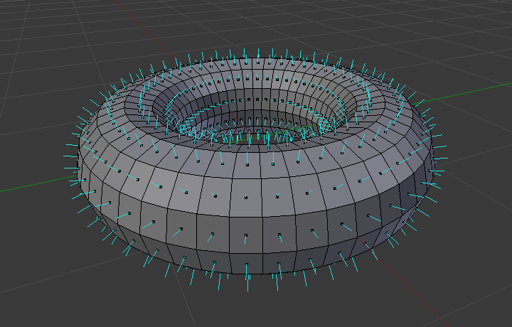
トーラスの面の法線のビジュアル
上の図において、それぞれの青い線がトーラスの面に対する法線を示しており、各面に対して垂直になっています。Editモードにおける Mesh Display Viewport Overlays panel において可視化を有効にできます。
プロパティー
参照
- Panel
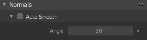
Normals panel.
- Auto Smooth
メッシュのパーツのシェーディングをsmoothに設定している場合に、面の間の角度が*Angle* ボタンでの指定よりも小さい辺について、スムーズにします。
- Angle
角度の数値フィールド
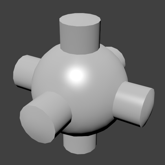
Auto Smooth を有効にしたメッシュの例
Advanced Smooth Shading & Sharp Edges
By default in Blender, with basic normal computing behavior, a sharp edge is always defined as an edge being either non-manifold, or having at least one of its faces defined as flat.
Enabling the Auto Smooth setting adds an extra parameter to define a sharp edge, the Angle threshold between two neighbor faces, above which the edge will always be considered as sharp.
Auto Smooth also enables Custom Split Normals handling, which can be either defined (and edited) as a mesh data layer, or generated on the fly by modifiers. In any case, when a mesh gets custom normals, they always supersede the default ones computed by Auto Smooth.
Sharp edges may still be used by the custom normals modifiers to compute their normals, depending on their settings.
Custom Split Normals
Custom Split Normals は、自動で計算されるデフォルトとは違う方向に向かって法線を指し示すことによってシェーディングを行う方法で、ゲーム開発でよく使われています。ゲーム開発では、ローポリオブジェクトによって発生するいくつかの問題を相殺するのに役立ちます。最もよくある例は、ローポリの木、ブッシュ、草などや、丸角です。
Blenderは、'smooth fan'ベースのカスタムnormalをサポートしています。'smooth fan'ベースとは、同じ頂点を共有しておりsmoothな辺で'リンクされている'隣接面の角のセットとして定義しています。つまり、面の角ごと、隣接面の角ごと、または頂点ごとに法線を持つことができます。
Custom Split Normalsを有効にする
参照
- モード
Editモード
- メニュー
Enables custom split normals.
Also, any of the custom normal editing tools (see below) will, as a convenience, enable custom normals if they are not already enabled.
注釈
This has the side effect of enabling Auto Smooth, as that is necessary to use custom normals. Once you have custom normals, the angle threshold of the Auto Smooth behavior is disabled -- all non-sharp-tagged edges will be considered as smooth, disregarding the angle between their faces.
Editing Custom Split Normals
参照
- モード
Editモード
- メニュー
- Hotkey
Alt-N
There are a number of tools for editing custom split normals. The custom normal mesh edit tools can affect all normals (the default), or only selected ones. To select a custom normal associated with a particular vertex and face:
Make the element selection mode both Vertex and Face (use Shift-LMB to enable the second one).
Select one or more vertices, then select a face. This can be repeated to select more vertices and a different face and so on. It is easiest to see the effect of these tools if you turn on the Edit Mode Overlays option Display vertex-per-face normals as lines.
参考
Importing Custom Split Normals
Some tools, particularly those used in CAD, tend to generate irregular geometry when tessellating their objects into meshes (very thin and long triangles, etc.). Auto-computed normals on such geometry often gives bad artifacts, so it is important to be able to import and use the normals as generated by the CAD tool itself.
注釈
Currently, only the FBX Importer and Alembic Importer are capable of importing custom normals.
トポロジー
ループ
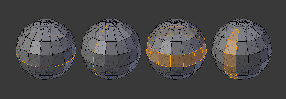
辺と面のループ
辺 と 面 のループは図 辺と面のループ で示すように連続した「ループ」を成す面や辺の集まりです。
上の図では、ポールに終わらないループはサイクリック(1と3)です。これらはループが始まった頂点でループが終わり、モデルを2つに分けます。特定の、連続的なメッシュ領域を扱う上で、ループは速くて強力なツールとして使え、有機的なキャラクター・アニメーションをする上で必須です。Blenderにおけるループの扱いに関する詳細については Edge Loop Selection を参照してください。
注釈
2と4で示したループがモデル全体を回らないことに注意してください。ループはポール(poles)と呼ばれるところで止まり、これはポール以降はループを一意に続ける方法がないからです。ポールは3つ、5つ、あるいはそれ以上の数の辺が接続されている頂点です。したがって、1つ、2つ、あるいは4つの辺が接続されている頂点はポールではありません。
辺ループ
図 辺と面のループ において、1と2で示したループは辺ループです。辺ループは頂点を繋げ、ループ上の各頂点において、ループ上にない2つの頂点に隣接し、その2つの頂点がループの両側に配置されるようにしています。(ポールがある場合の始点と終点は例外です)
有機的な(サブサーフェスを使った)モデリングやキャラクターでは、辺ループは特に重要な概念です。適切に使えば、サブディビジョンサーフェスで使うととても自然に見えるモデルを比較的少数の頂点で作れますし、アニメーションにおいても綺麗に変形します。
例として図 辺と面のループ を有機モデリングとして捉えてみましょう。辺ループは皮膚やその下の筋肉の自然な輪郭や変形の線に沿って走り、キャラクターが動く時により大きく変形するところ(例えば、肩や膝など)では密度がより高くなります。
より詳細な辺ループの扱い方は 辺ループ選択 を参照してください。
面ループ
面ループは辺ループの理論的な拡張であり、図 辺と面のループ の3と4で示すように2つの辺ループの間の面から成ります。4で示すように、循環しないループではポールを含む面は面ループに含まれないことに注意してください。
より詳細な面ループの扱い方は 面ループ選択 を参照してください。
ポール (Pole)
N-poles & E-poles を参照ください。
非多様体 (Non-Manifold)
Non-manifold を参照ください。