Bevel Modifier(ベベルモディファイアー)
The Bevel modifier bevels the edges of the mesh it is applied to, with some control of how and where the bevel is applied to the mesh.
It is a non-destructive alternative to the Bevel Operation in Edit Mode.
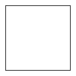
Not beveled. |
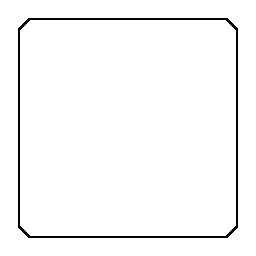
Beveled. |
Options(オプション)
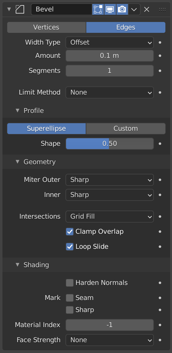
The Bevel modifier.
- Affect(影響)
- Vertices(頂点)
頂点の近くの領域のみがベベルされ、辺は変更されません。
- Edges(辺)
辺をベベルして、頂点に交差を作成します。
Three cubes with 0.1, 0.3 and 0.5 bevel widths, with Vertices option selected.
- Width Type
Defines how Width will be interpreted to determine the amount of bevel.
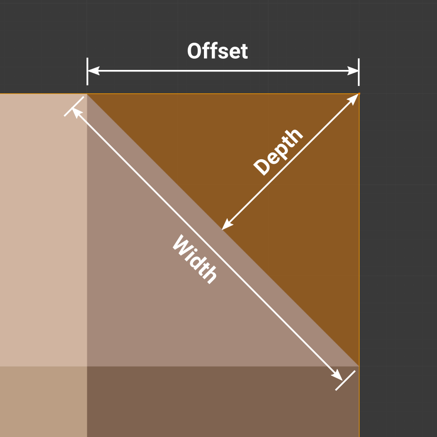
- Offset(オフセット)
新しい辺から元の辺までの距離。
- Width(幅)
ベベルによって形成された2つの新しい辺(または、複数のセグメントがある場合はベベルの両側の辺)間の距離。
- Depth(深度)
Value is the perpendicular distance from the new bevel face to original edge.
- Percent(%)
The percentage of the length of adjacent edge length that the new edges slide along.
- Absolute(絶対)
ベベルした辺に隣接する辺に沿った正確な距離。ベベルした辺に接続したベベルしていない辺が直角以外の角度で交わる場合、 Offset(オフセット) との違いがわかります。
- Width(幅)
The size of the bevel effect. See Width Method below.
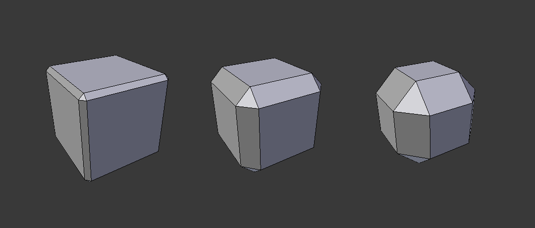
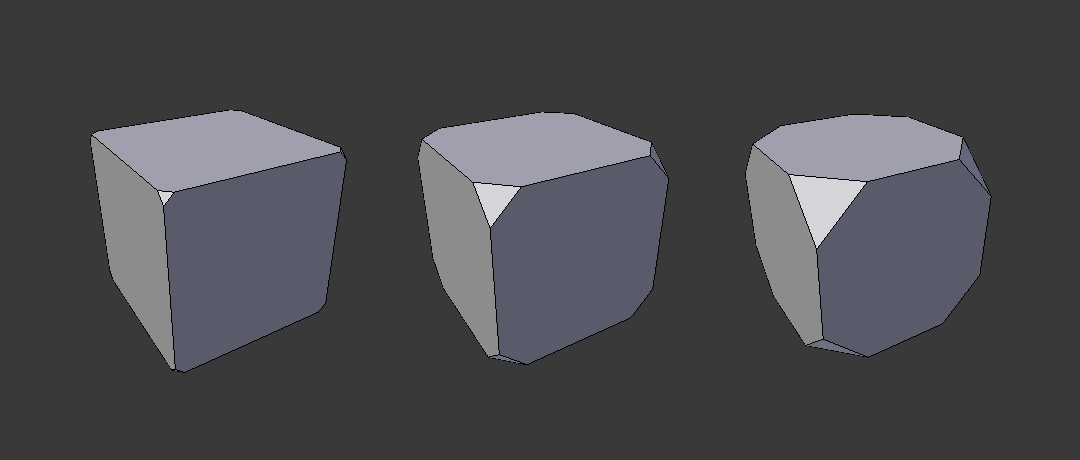
Three Cubes with 0.1, 0.3 and 0.5 bevel widths.
- Segments(セグメント)
The number of edge loops added along the bevel's face.
- Limit Method
Used to control where a bevel is applied to the mesh.
- None(なし)
No limit, all edges will be beveled.
- Angle(角度)
Only bevels edges whose angle of adjacent face normals plus the defined Angle is less than 180 degrees. Intended to allow you to bevel only the sharp edges of an object without affecting its smooth surfaces.
- Weight(ウェイト)
Use each edge's bevel weight to determine the width of the bevel. When the bevel weight is 0.0, no bevel is applied. See here about adjusting bevel weights.
- Vertex Group(頂点グループ)
Use weights from a vertex group to determine the width of the bevel. When the vertex weight is 0.0, no bevel is applied. An edge is only beveled if both of its vertices are in the vertex group. See here about adjusting vertex group weights.
- Invert(反転)
<-> Inverts the influence of the selected vertex group, meaning that the group now represents vertices that will not be deformed by the modifier.
The setting reverses the weight values of the group.
- Invert(反転)
Profile
Superellipse(ラメ曲線)
均一な凹曲線または凸曲線のベベルを作成します。
- Shape
The shape of the bevel, from concave to convex. It has no effect if Segments is less than 2.
Custom Profile
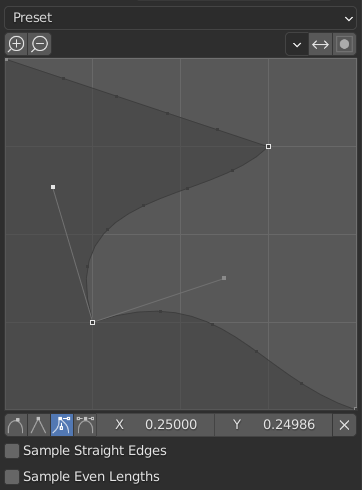
カスタムプロファイルウィジェット。
- Miter Shape
The shape of the miter patterns, from concave to convex. It has no effect if Segments is less than 2.
注釈
The Miter Shape slider stays active when miters are enabled because it still controls the shape of the miter profiles.
このウィジェットを使用すると、単一のプロファイルパラメータよりも複雑なユーザー定義プロファイルを作成できます。モーダルツールを使用すると、カスタムプロファイルを切り替えることができますが、プロファイルの形状は、操作が確認された後にのみオプションパネルで編集できます。
The profile starts at the bottom right of the widget and ends at the top left, as if it were between two edges meeting at a right angle. Control points are created in the widget and then the path is sampled with the number of segments from the Bevel modifier.
- Presets(プリセット)
Support Loops(サポートループ) および Steps(ステップ) プリセットはベベル内のセグメントの数に応じて動的に構築されています。セグメント数を変更する場合は、プリセットを再適用する必要があります。
- Sampling(サンプリング)
Samples will first be added to each control point, then if there are enough samples, they will be divided evenly between the edges. The Sample Straight Edges option toggles whether the samples are added to edges with sharp control points on either side. If there aren't enough samples to give each edge the same number of samples, they will just be added to the most curved edges, so it is recommended to use at least as many segments as there are control points.
Geometry(ジオメトリ)
- Miter Inner/Outer
A miter is formed when two beveled edges meet at an angle. On the side where the angle is greater than 180 degrees, if any, it is called an outer miter. If it is less than 180 degrees, then it is called an inner miter. The outer and inner miters can each be set to one of these patterns:
- Sharp(シャープ)
辺は鋭いポイントで交わり、辺に余分な頂点が導入されることはありません。
- Patch(パッチ)
Edges meet at a sharp point but in addition, two extra vertices are introduced near the point so that the edges and faces at the vertex may be less pinched together than what occurs in the Sharp case. This pattern does makes no sense for inner miters, so it behaves like Arc for them.
The Spread slider controls how far the new vertices are from the meeting point.
- Arc(弧)
Two vertices are introduced near the meeting point, and a curved arc joins them together.
The Spread slider controls how far the new vertices are from the meeting point.
The Profile slider controls the shape of the arc.
Diagrams of the miter patterns. 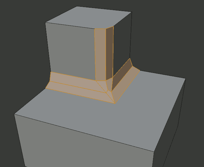
Sharp(シャープ)でのOuter Miter(外側)。
Patch(パッチ)でのOuter Miter(外側)。
Arc(弧)でのOuter Miter(外側)。

Sharp(シャープ)でのInner Miter(内側)。
Arc(弧)でのInner Miter(内側)。
- Spread(広がり)
The value used to spread extra vertices apart for non-sharp miters.
- Intersections
3つ以上のベベルする辺が頂点で交わる場合、生成されたジオメトリ間の交差を完成させる方法としてメッシュが作成されます。このオプションは、そのメッシュの作成に使用するメソッドを制御します。
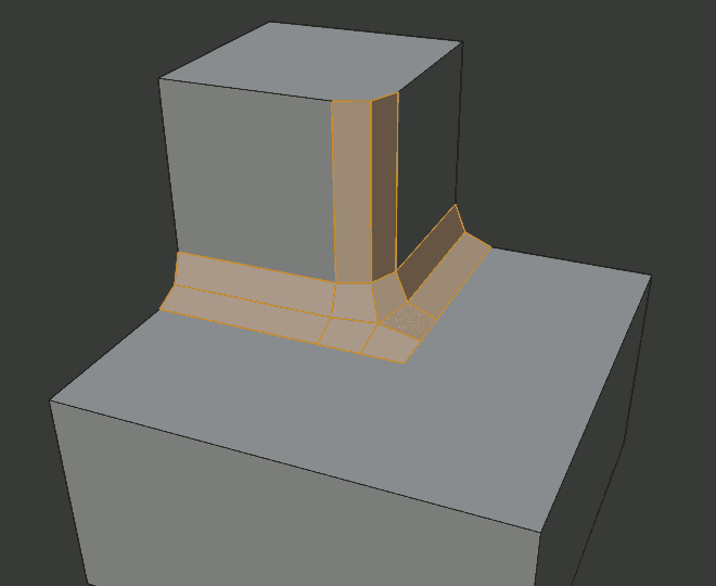
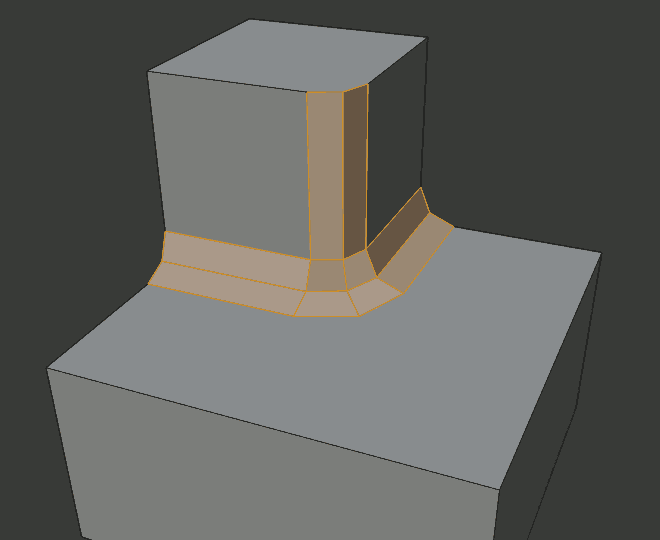
- Grid Fill(グリッドフィル)
The default method for building intersections, useful when a smooth continuation of the bevel profile is desired. Without Custom Profile enabled, the curve of the profile continues through the intersection, but with a custom profile it just creates a smooth grid within the boundary of the intersection.
- Cutoff(カットオフ)
頂点に入る各ベベルする辺の端に Cutoff(カットオフ) 面を作成します。これは、新しい交差が複雑すぎてスムーズな Grid Fill(グリッドフィル) ができないカスタム断面に最も役立ちます。
三叉路では、Cutoff(カットオフ)断面の内側の角が同じ位置で交わる場合、中心面は作成されません。
カットオフ面の方向は、元の頂点の法線によって異なります。
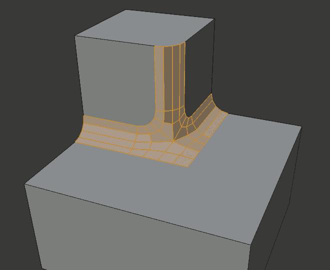
Intersection(交差)方法のオプション。 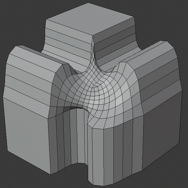
Grid fill(グリッドフィル) 交差。
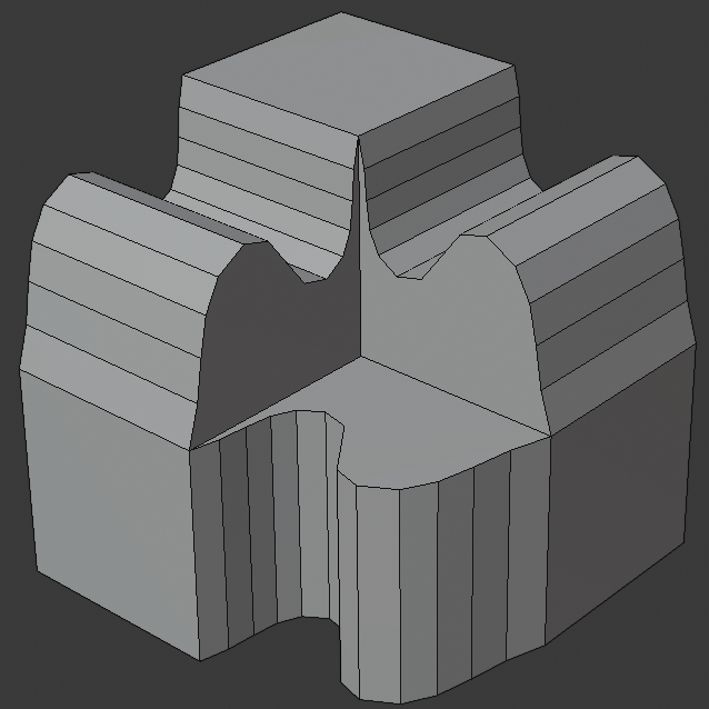
内側の頂点が交わる、三叉路の Cutoff(カットオフ) 交差。

中心面を持つ、Cutoff(カットオフ) 交差。
- Clamp Overlap
辺が他のジオメトリと重ならないように、それぞれのベベルした辺の幅を制限します。
- Loop Slide(ループスライド)
If there are unbeveled edges along with beveled edges into a vertex, the bevel tries to slide along those edges when possible. Turning the option off can lead to more even bevel widths.
Shading(シェーディング)
- Harden Normals
When enabled, the per-vertex face normals of the bevel faces are adjusted to match the surrounding faces, and the normals of the surrounding faces are not affected. This will keep the surrounding faces flat (if they were before), with the bevel faces shading smoothly into them. For this effect to work, you need custom normals data, which requires Auto Smooth option to be enabled (see Normals).
- Mark(マーク)
- Seam(シーム)
シーム辺がシームでない辺と交差し、それらすべてをベベルする場合、このオプションはシームの予想される伝播を維持します。
- Sharp(シャープ)
Mark Seams(シームをマーク)と同様ですが、シャープな辺用です。
- Material Index(マテリアルインデックス)
The index of the material slot to use for the bevel. When set to -1, the material of the nearest original face will be used.
- Face Strength(面の強さ)
Set Face Strength on the faces involved in the bevel, according to the mode specified here. This can be used in conjunction with a following Weighted Normals modifier (with the Face Influence option checked).
- None(なし)
面の強さを設定しない。
- New(新規)
辺に沿った新しい面の面の強さを Medium(中) に設定し、頂点の新しい面の面の強さを Weak(弱) に設定します。
- Affected(影響する物)
New(新規) に設定されているものに加えて、新しい面に隣接する面にも強さを Strong(強) に設定します。
- All(全て)
In addition to those set for the Affected case, also set all the rest of the faces of the model to have strength Strong.