ノードを構成するパーツ
ノードの種類 を問わず、Blenderのすべてのノードは、似通った構造に基づいています。ノードのパーツには、タイトル、ソケット、プレビューなどが含まれます。
タイトル
タイトルはノードの名前/タイプを示し、 Label(ラベル) を変更することでオーバーライドできます。タイトルの左側には、ノードを折りたたむために使用できる 折りたたみ トグルがあります。これは、 H を使用して実行することもできます。
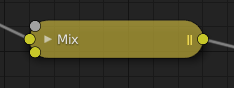
折りたたんだノードの表示状態。
ソケット
The sockets input and output values from the node. They appear as little colored circles on either side of the node. Unused sockets can be hidden with Ctrl-H. There are two kinds of sockets: inputs and outputs.
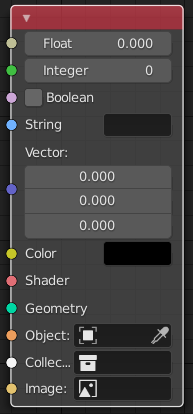
各ソケットは、処理するデータの種類に対応した色が付けられています。
- Float (グレー)
Indicates numeric value's information. It can either be a single numerical value or a so-called "value map". (You can think of a value map as a gray-scale map where the different amount of bright/dark reflects the value for each point.) If a single value is used as an input for a "value map" socket, all points of the map are set to this same value. Common use: Alpha maps and value options for a node.
- Integer (ライムグリーン)
整数値(小数成分のない数値)を渡すために使用されます。
- Boolean(ブーリアン) (ピンク)
trueまたはfalseの値を渡すために使用されます。
- String (水色)
テキスト値を渡すために使用されます。
- Vector(ベクトル) (濃紺)
ベクトル、座標、法線情報を示します。
- Color(カラー) (黄)
Indicates that color information needs to be input or will be output from the node. Depending on the node tree type, the color has an alpha channel or not.
- Shader(シェーダー) (緑)
- Geometry(ジオメトリ) (ターコイズ)
Geometry Nodes(ジオメトリノード) で使用されます。
- Object(オブジェクト) (オレンジ)
オブジェクトデータブロックを渡すために使用されます。
- Collection(コレクション) (白)
コレクションデータブロックを渡すために使用されます。
- Image(画像) (アプリコット)
画像データブロックを渡すために使用されます。
入力
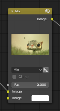
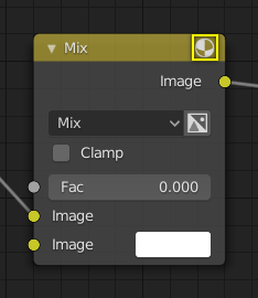
The inputs are located on bottom left side of the node, and provide the data the node needs to perform its function. Each input socket, except for the green shader input, when disconnected, has a default value which can be edited via a color, numeric, or vector interface input. In the screenshot of the node above, the second color option is set by a color interface input.
Some nodes have special sockets that can accept multiple inputs into a single socket. These sockets will have an ellipsis shape rather than a circle to indicate its special behavior.
出力
出力はノードの右上にあり、ノードツリーのさらに下流のノードが持つ入力へ接続できます。
Conversion(変換)
Some socket types can be converted to other socket types either implicitly or explicitly. Implicit conversion can happen automatically without the need of a conversion node.
For example, color and float sockets can both be placed into one another. Once a socket conversion is made data may be lost and cannot be retrieved later down the node tree. Implicit socket conversion can sometimes change the data units as well. When plugging a Value input node into an angle socket will default to use radians regardless of the scene Units(単位). This happens because the Value node has no unit while the angle input does.
有効な変換:
Between color and vector -- in this case the using individual color channels to store the vector.
Between color and float -- the color data is converted to its gray scale equivalent.
カラー/float/ベクトルからシェーダへの変換 -- 暗黙的に色に変換され、Emission(放射) ノードを使用した結果が得られます。
Explicit conversion requires the use of a conversion node for example the Shader To RGB (シェーダーからRGBへ) node or the RGB to BW(RGBからBWへ)ノード node. The Math(数式)ノード node also contains some functions to convert between degrees and radians.
Properties(プロパティ)
多くのノードには、入力と出力の関係に影響を与える設定があります。ノード設定は、出力の下から入力の上にかけて表示されます。
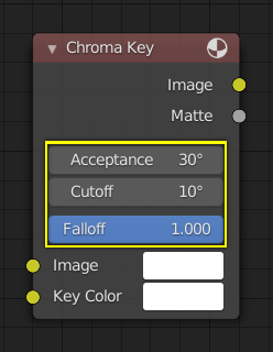
クロマキーノードでのコントロールの例。
Preview(プレビュー)
On some nodes this shows a preview image of how the output data for a certain channel will appear. Usually it shows color data.
The preview can be toggled using the icon on the very top right-hand corner of the node, next to the title.
プレビューを表示していないノードの図。