Составляющие узла
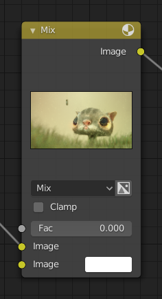
Все узлы в Blender основаны на аналогичной конструкции. Это относится к любому типу узлов. Эти части включают заголовок, порты, предварительный просмотр и многое другое.

Заголовок
Заголовок показывает имя/тип узла; его можно переопределить, изменив Метку узла. Слева от заголовка находится переключатель свёртывания, который можно использовать для сворачивания узла. Это также можно сделать с помощью клавиши H.

Внешний вид узла в свёрнутом состоянии.
Порты

Sockets are input and output values for the node. They appear as little colored circles on either side of the node. Unused sockets can be hidden with Ctrl-H.
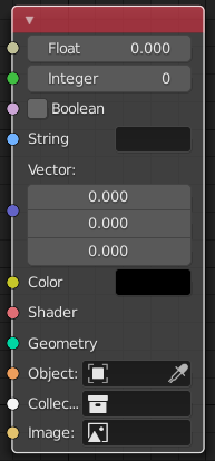
Каждый порт имеет цветовую маркировку в зависимости от типа данных, которые он обрабатывает.
- Вещественное (серый)
Indicates that the socket accepts/produces floating-point numbers. It can either be a single value or a so-called «value map». (You can think of a value map as a grayscale image where the brightness of a pixel represents its value.) If a single value is used as an input for a «value map» socket, all points of the map are set to this same value.
- Целое (зелёный)
Используется для передачи целочисленного значения (числа без дробной части).
- Логический (розовый)
Используется для передачи истинного или ложного значения.
- Строковой (голубой)
Используется для передачи текстового значения.
- Вектор (тёмно-синий)
Указывает информацию о векторе, координатах и нормали.
- Цвет (жёлтый)
Indicates that the socket accepts/produces color information. The colors may or may not have an alpha component depending on the node tree type.
- Шейдер (светло-красный)
- Geometry (turquoise)
Используется в Узлах геометрии.
- Объект (оранжевый)
Используется для передачи блока данных объекта.
- Колекция (белый)
Используется для передачи блока данных коллекции.
- Изображение (абрикосовый)
Используется для передачи блока данных изображения.
Входы
The inputs are located on the bottom left side of the node, and provide the data the node needs to perform its function. Each input socket, except for the green shader input, when disconnected, has a default value which can be edited via a color, numeric, or vector interface input. In the screenshot of the node above, the second color option is set by a color interface input.
Some nodes have special sockets that can accept multiple inputs. These sockets will have an ellipsis shape rather than a circle to indicate their special behavior.
Выходы
Выходы расположены в верхней правой части узла и могут быть подключены к входам узлов, расположенных дальше по дереву узлов.
Преобразование
Some socket types can be converted to others either implicitly or explicitly. Implicit conversion happens automatically without the need of a conversion node. For example, Float sockets and Color sockets can be linked to each other.
Once a socket conversion is made, data may be lost and cannot be retrieved later down the node tree. Implicit socket conversion can sometimes change the data units as well. When plugging a Value input node into an angle socket, it’ll default to use radians regardless of the scene’s Единицы измерений. This happens because the Value node has no unit while the angle input does.
Правильные преобразования:
Between color and vector – mapping between color channels and vector components.
Between color and float – the color data is converted to its grayscale equivalent.
Цвет/вещественные/вектора в шейдер — неявно преобразует в цвет и даёт результат использования узла Emission.
Explicit conversion requires the use of a conversion node such as the Shader To RGB node or the Узел RGB to BW node. The Узел Math node also contains some functions to convert between degrees and radians.
Свойства
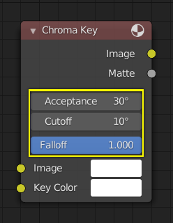
Многие узлы имеют настройки, которые могут повлиять на то, как они взаимодействуют с входами и выходами. Настройки узла расположены ниже выходов и выше любых входов.

Пример элементов управления узла Chroma Key.
Предпросмотр
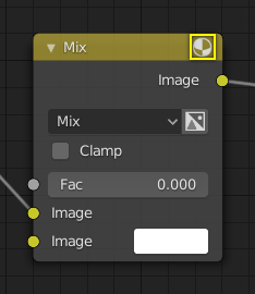
Some nodes can show an image that previews their result. The preview can be toggled using the icon on the very top right-hand corner of the node, next to the title.

Как узел выглядит без предварительного просмотра.