Textures
Textures are...
Textures
Relevant to Blender v2.31 MISSING AL NEW STUFF!
The material settings that we've seen up to now produce nice, smooth, uniform objects. Of course, such objects are never true to reality, where disuniformities are most common.
Blender accounts for these disuniformities, whether in color, reflective or specular power, roughness, and so on, via textures.
Textures from the Material Point of View
In Blender, the Materials and Textures form separate blocks in order to keep the interface simple and to allow universal integration between Textures, Lamps, and World blocks.
The relationship between a Material and a Texture, called the 'mapping,' is two-sided. First, the information that is passed on to the Texture must be specified. Then the effect of the Texture on the Material is specified. The Texture panel on the right-hand side (and similar panels exist for the the Lamp and World buttons) defines all these calculations.
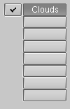
For an untextured material the panel shows a column of eight empty texture channels (Figure 1), by selecting one and pressing Add New or by selecting an existing texture with the MenuButton right below (Figure 2) you add a texture and the Panel shows two more tabs: Map Input and Map To. The Tabs buttons are organized in the sequence in which the 'texture pipeline' is performed.
Each channel has its own individual mapping. By default, textures are executed one after another and then superimposed. As a result, an added second Texture channel can completely replace the first one! Next to each non-empty texture channel a check button allows you to select or de-select a given channel. De-selected channels are simply removed from the pipeline.
The Texture itself is designated by its name, which you can edit in the Text Button above the Texture selection MenuButton.
Figure 3 shows the Map Input panel. Each Texture has a 3D coordinate (the texture coordinate) as input. The values, passed to the texture as coordinates for each pixel of the rendered image belonging to a given material, are computed according to these buttons:
UV Uses a special kind of mapping called 'UV' mapping. This is especially useful when using images as textures, as we'll see in the Section called UV Editor and FaceSelect.
Object Uses an Object as source of coordinates; usually an Empty. The Object name must be specified in the text button on the right. This is the preferred way to place a small image as a logo or whatever at a given point on the object.
Glob Uses Blender Global 3D coordinates.
Orco Uses the Object local, original, coordinates.
Stick Uses the Object local, sticky, coordinates.
Win Uses the rendered image window coordinates.
Nor Uses the direction of the normal vector as coordinates.
Refl Uses the direction of the reflection vector as coordinates.
If the texture is an image it is 2D, and we must map the 3D space onto it. The most flexible way to do so is with UV mapping, otherwise four possible pre-set mappings are provided (Figure 4).
The X, Y and Z coordinates passed to the texture can be shuffled about to obtain special effects. The buttons in Figure 5 allow you to switch X into Y or Z and so on, or to turn them off.
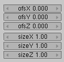
Coordinates can be scaled and translated by assigning an offset (Figure 6).
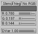
Moving to the Map To tab, Figure 7 shows the texture input settings. The three buttons determine whether the texture should be used as a Stencil (a Mask for subsequent texture channels); a Negative texture (assigning negative, rather than positive, values); or as a black and white (No RGB), intensity only, texture. The three sliders below these buttons define the texture base color, which can be overridden by color specifications inside the texture definition. Finally the last slider defines the intensity of the texture effect.
Figure 8 shows the toggle buttons which determine which characteristic of the material will be affected by the texture. Some of these button are three state buttons, meaning that the texture can be applied as positive or negative. All of these buttons are independent.
Col (on/off) Uses the texture to alter the Material color.
Nor (off/positive/negative) Uses the texture to alter the direction of the local normal. This is used to fake surface imperfections or unevenness via bump mapping.
Csp (on/off) Uses the texture to alter the Specular color.
Cmir (on/off) Uses the texture to alter the Mirror color.
Ref, Spec, Hard, Alpha, Emit (off/positive/negative) Uses the texture to alter the Corresponding Material value.
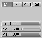
The output settings (Figure 9) determine the strength of the effect of the Texture output. Mixing is possible with a standard value, including addition, subtraction, or multiplication. Textures give three types of output:
RGB textures: return three values, which always affect color.
Bump textures: return three values, which always affect the normal vector. Only the "Stucci" and "Image" texture can give normals.
Intensity textures: return a single value. This intensity can control "Alpha," for example, or determine the strength of a color specified using the mapping buttons.
You can adjust the intensity of these settings separately using the pertinent sliders (Figure 9).
Textures themselves
Once a new texture has been added to a material, it can be defined by
switching to the Texture Buttons (F6) or
 sub-context of the Shading context to obtain Figure 10.
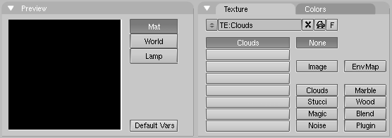
A new, empty texture Button Window presents two panels: a Texture Preview and a Texture panel, the latter with two tabs.
In the Preview panel toggle buttons define if this is a Material, Lamp or World texture, and a button Default Var allows to return texture parameters to default values.
The Texture tab replicates the texture channels and the Texture Menu Button of the linked Material. The two columns of Toggle Buttons selects the Texture type. The button Image allows an image to be loaded and used as a texture (the first button simply is "no texture"). The third button allows for the use of a very special kind of texture, the Environment Map (EnvMap). The last button (Plugin) allows for loading an external piece of code to define the texture. (These three buttons are rather unique and will be treated separately later on.) As soon as a texture type is chosen a new Panel appears, with a name matching the texture type, where texture parameters can be set.
The remaining buttons define 3D procedural textures, which are textures that are defined mathematically. They are generally simpler to use, and will give outstanding results once mastered. We will describe just one of these, the Wood button, leaving you to investigate further. (The reference chapter in this book contains a full details on each.)
Wood is a procedural, which means that each 3D coordinate can be translated directly into a color or a value. These types of textures are 'real' 3D. By that we mean that they fit together perfectly at the edges and continue to look like what they are meant to look like even when they are cut; as if a block of wood had really been cut in two.
Procedural textures are not filtered or anti-aliased. This is hardly ever a problem: the user can easily keep the specified frequencies within acceptable limits.
Procedural texture can either produce colored textures or intensity only textures. If intensity only ones are used the result is a black and white texture, which can be greately enhanced by the use of colorbands. The colorband is an often-neglected tool in the Colors tab in the Texture Panel that gives you an impressive level of control over how procedural textures are rendered. Instead of simply rendering each texture as a linear progression from 0.0 to 1.0, you can use the colorband to create a gradient which progresses through as many variations of color and transparency (alpha) as you like (Figure 11).
Skilled use of colorbands leads to really cool marble and cloud textures. To use it, select a procedural texture, such as Wood. Click the Colorband button.
The Colorband is Blender's gradient editor. Each point on the band can be placed at any location and can be assigned any color and transparency. Blender will interpolate the values from one point to the next. To use it, select the point you want to edit with the Cur: number button, then add and delete points with the Add and Del buttons. The RGB and Alpha values of the current point are displayed, along with the point's location on the band. Drag with the left mouse to change the location of the current point.
We can use two Wood textures to make ring patterns in two different scales, each of which will have different effects on the appearance of the wood. The Wood textures are identical except for the way in which they are mapped in the material buttons window, and in the different color bands used.
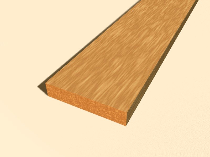
We will also also use a Clouds texture to make a grain pattern. To see the result of just one texture, isolated from the others, remember the Check buttons in the Texture Panel in Material Buttons.
 | Copying texture settings |
|---|---|
By adding an existing texture you link that texture, but all the Material mapping parameters remains as they are. To copy all texture settings, inclusive of mappings, you must copy a given texture channel and paste it into another by using the two arrow buttons in Figure 12. |
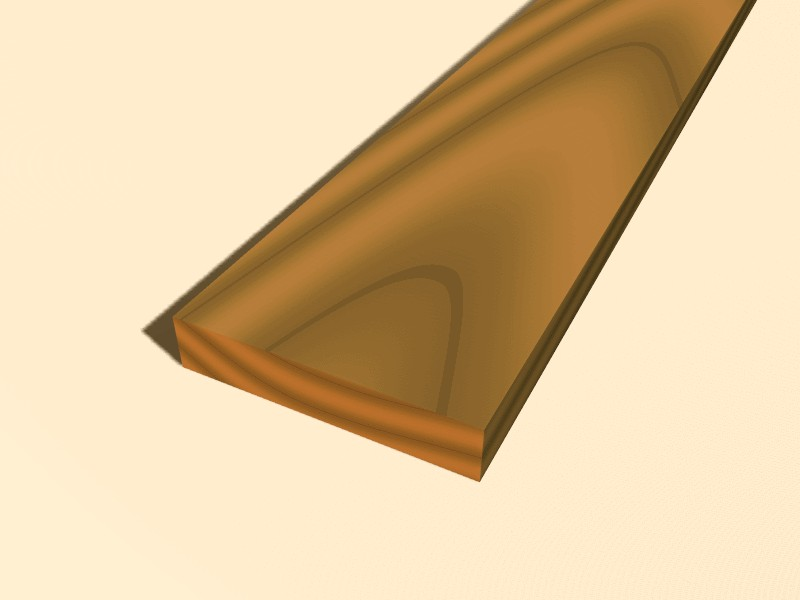
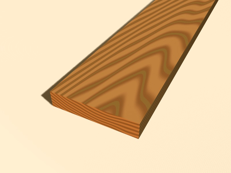
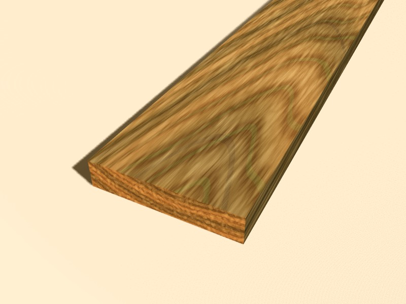
Figure 13, Figure 14 and Figure 15 show the three individual textures which, when combined in a single material and mapped to various material parameters, create a nice wood texture (Figure 16).
ImageTexture
The Image texture is the only true 2D texture, and is the most frequently used and most advanced of Blender's textures. The standard, built-in bump mapping and perspective-corrected mip-mapping, filtering, and anti-aliasing guarantee outstanding images (set DisplayButtons OSA to ON for this). Because pictures are two-dimensional, the way in which the 3D texture coordinate is translated to 2D must be specified in the mapping buttons (Figure 4 in the Section called Textures from the Material Point of View).
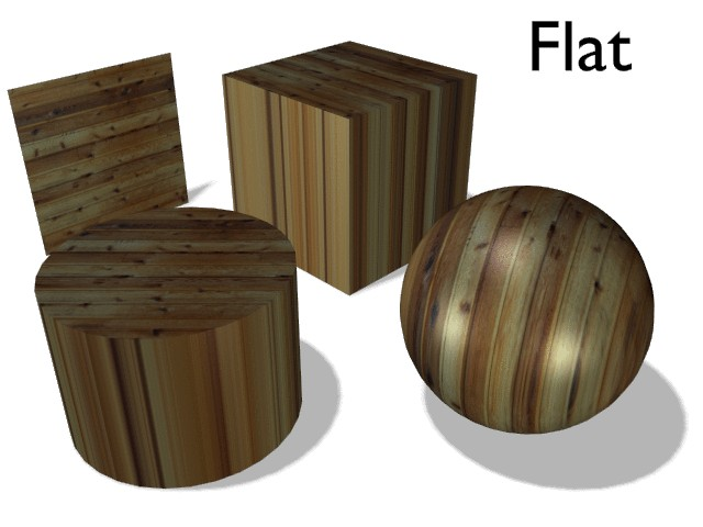
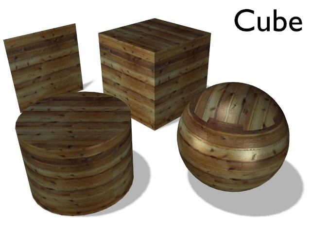
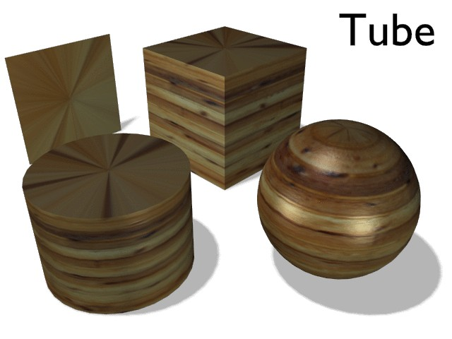
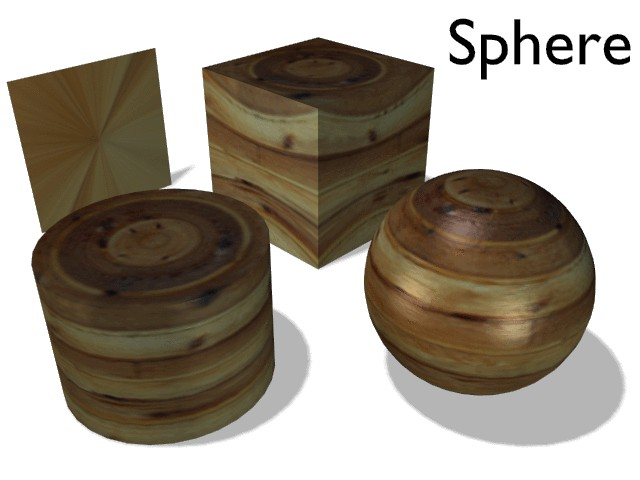
The four standard mappings are: Flat, Cube, Tube and Sphere. Depending on the overall shape of the object, one of these types is more useful.
The Flat mapping (Figure 17) gives the best results on single planar faces. It does produce interesting effects on the sphere, but compared to a sphere-mapped sphere the result looks flat. On faces not in the mapping plane the last pixel of the texture is repeated, which produces stripes on the cube and cylinder.
The cube-mapping (Figure 18) often gives the most useful results when the objects are not too curvy and organic (notice the seams on the sphere).
The tube-mapping (Figure 19) maps the texture around an object like a label on a bottle. The texture is therefore more stretched on the cylinder. This mapping is of course very good for making the label on a bottle or assigning stickers to rounded objects. However, this is not a cylindrical mapping so the ends of the cylinder are undefined.
The sphere-mapping (Figure 20) is the best type for mapping a sphere, and it is perfect for making a planet and similar stuff. It is often very useful for creating organic objects. It too produces interesting effects on a cylinder.
 | Moving a texture |
|---|---|
As described in the previous section you can manipulate the texture in the texture part of the MaterialButtons. There is one more important feature to manipulate the textures. When you select an object and press TKEY, you get the option to visually scale and move the texture space, but not to rotate the texture. The Object coordinate mapping is anyway much more flexible. |
