Normals
Introduction
In geometry, a normal is a direction or line that is perpendicular to something, typically a triangle or surface but can also be relative to a line, a tangent line for a point on a curve, or a tangent plane for a point on a surface.
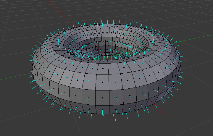
A visualization of the face normals of a torus.
In the figure above, each blue line represents the normal for a face on the torus. The lines are each perpendicular to the face on which they lie. The visualization can be activated in the Mesh Display panel.
Shading
Reference
| Mode: | Object Mode |
|---|---|
| Panel: |
Reference
| Mode: | Edit Mode |
|---|---|
| Panel: | |
| Menu: |
Flat

|
|
As seen in the previous sections, polygons are central to Blender. Most objects are represented by polygons and truly curved objects are often approximated by polygon meshes. When rendering images, you may notice that these polygons appear as a series of small, flat faces. Sometimes this is a desirable effect, but usually we want our objects to look nice and smooth.
Smooth

Shading buttons in the Tool Shelf.
The easiest way is to set an entire object as smooth or faceted by selecting a mesh object, and in Object Mode, click Smooth in the Tool Shelf. This button does not stay pressed; it forces the assignment of the “smoothing” attribute to each face in the mesh, including when you add or delete geometry.
Notice that the outline of the object is still strongly faceted. Activating the smoothing features does not actually modify the object’s geometry; it changes the way the shading is calculated across the surfaces (normals will be interpolated), giving the illusion of a smooth surface.
Click the Flat button in the Tool Shelf’s Shading panel to revert the shading back (normals will be constant) to that shown in the first image above.
Smoothing Parts of a Mesh
Alternatively, you can choose which edges to smooth by entering Edit Mode, then selecting some faces and clicking the Smooth button. The selected edges are marked in yellow.
When the mesh is in Edit Mode, only the selected edges will receive the “smoothing” attribute. You can set edges as flat (removing the “smoothing” attribute) in the same way by selecting edges and clicking the Flat button.
See also
The Auto Smooth filter is a quick and easy way to combine smooth and faceted faces in the same object.
Properties
Reference
| Panel: |
|---|
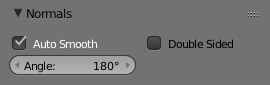
Normals panel.
- Auto Smooth
Edges where an angle between the faces is smaller than specified in the Angle button will be smoothed, when shading of these parts of the mesh is set to smooth. This is an easier way to combine smooth and sharp edges.
- Angle
- Angle number button.
- Double Sided
- Lighting with positive normals on back-faces of the mesh in the viewport (OpenGL).
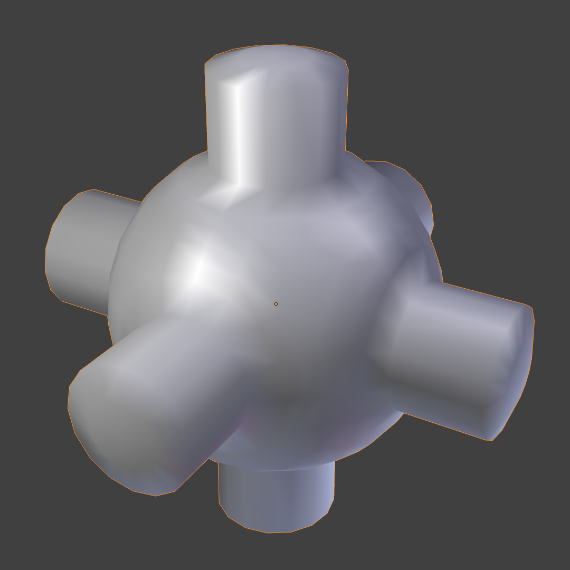
Example
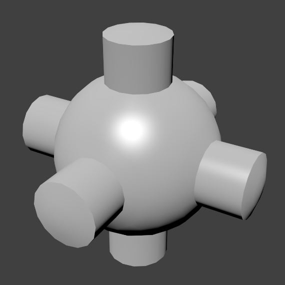
Example mesh with Auto Smooth enabled.
See also
Edge Split Modifier
With the Edge Split Modifier a result similar to Auto Smooth can be achieved with the ability to choose which edges should be split, based on angle.
Editing
Flip Direction
Reference
| Mode: | Edit Mode |
|---|---|
| Panel: | |
| Menu: | or |
Well, it will just reverse the normals direction of all selected faces. Note that this allows you to precisely control the direction (not the orientation, which is always perpendicular to the face) of your normals, as only selected ones are flipped.
Recalculate Normals
Reference
| Mode: | Edit Mode |
|---|---|
| Panel: | |
| Menu: | and |
| Hotkey: | Ctrl-N and Shift-Ctrl-N |
These tools will recalculate the normals of selected faces so that they point outside (respectively inside) the volume that the face belongs to. This volume do not need to be closed. In fact, this means that the face of interest must be adjacent with at least one non-coplanar other face. For example, with a Grid primitive, recalculating normals does not have a meaningful result.
Set from Face
Reference
| Mode: | Edit Mode |
|---|---|
| Panel: |
Sets the custom vertex normals from the selected face’s normals.
Custom Split Normals
Custom Split Normals is a way to tweak/fake shading by pointing them towards other directions than default, auto-computed ones. It is mostly used in game development, where it allows to counterbalance some issues generated by low-poly objects (the most common examples are low-poly trees/bushes/grass/etc., and the ‘rounded’ corners).
Blender supports custom normals on a ‘smooth fan’ base, defined as a set of neighbor face corners sharing the same vertex and ‘linked’ by smooth edges. This means you can have normals per face corners, per a set of neighbor face corners, or per vertex.
Enabling Custom Split Normals Support
- Enable custom split normals using Add Custom Split Normals Data.
- Make sure to enable Auto Smooth.
Note
Once you have custom normals, the angle threshold of the Auto Smooth behavior is disabled – all non-sharp-tagged edges will be considered as smooth, disregarding the angle between their faces.
Creating/Editing Custom Split Normals
Currently, editing is only possible by using the Normal Edit Modifier.
You can also copy normals from another mesh using Data Transfer (operator or modifier).
Importing Custom Split Normals
Some tools, in particular CAD ones, tends to generate irregular geometry when tessellating their objects into meshes (very thin and long triangles, etc.). Auto-computed normals on such geometry often gives bad artifacts, so it is important to be able to import and use the normals as generated by the CAD tool itself.
Note
Currently, only the FBX importer is capable of importing custom normals.