Design Tools (Herramientas de diseño)
El menú de herramientas PDT:
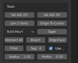
Esta sección del menú trata con las herramientas, que trabajan con sus propias variables en algunos casos, éstas también usan el plano de trabajo (Working Plane).
Set A/D 2D:
Este botón será utilizado para medir el ángulo relativo a la horizontal en el plano de trabajo determinado por dos vértices o dos objetos. Se podrá ver una lista completa de opciones disponibles en la tabla de la página anterior (Antes de comenzar) para los modos Editar y Objeto. Aquí la opción ``Working Plane``(Plano de trabajo) será importante porque, si se configura en ``Vista` `, la salida se calculará en relación con los ejes locales de la vista (resultando independiente de cómo esté orientada la misma), de lo contrario, funcionará en relación a los ejes globales de la vista.
Output: Sets the Distance, Angle, X, Y & Z input variables.
Selección: en Modo de Edición seleccione dos vértices con el ratón, el vértice Activo se considera el centro de rotación o punto de apoyo. En el modo de Objeto, el objeto Activo se considera de manera similar.
Example 1: Set the Input variables to two vertices in Edit Mode in Front view,
set Working Plane to Front, select the rotational vertex, select the center vertex.
The Distance variable is set to the apparent separation fo the two vertices in the front view,
the Angle is set to the apparent angle relative to horizontal in the front view, the X, Y & Z
inputs are set to the delta offset between the two vertices in the view axes.
Example 2: Set the Input variables to two objects in Object Mode in Top view,
set Working Plane to Top(X-Y), select the rotational object, select the center object.
The Distance variable is set to the apparent separation of the two objects in the top view,
the Angle is set to the apparent angle relative to horizontal in the top view, the X, Y & Z
inputs are set to the delta offset between the two vertices in the view axes.
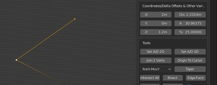
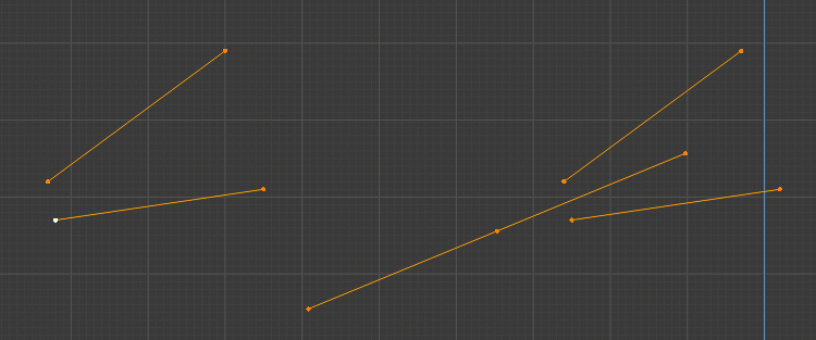
Parameters set from two Vertices in Front Working Plane.
Set A/D 3D:
Este botón se utiliza para medir el ángulo determinado por tres vértices o tres objetos. Se puede ver una lista completa de opciones disponibles en la tabla de la página anterior (Antes de comenzar) para los modos Editar y Objeto. Aquí la configuración del Plano de trabajo es irrelevante porque el ángulo se calcula en espacio 3D.
Output: Sets the Distance, Angle, X, Y & Z input variables.
Selección: en modo Edición se selecciona tres vértices con el ratón, el vértice Activo se considera el centro de rotación o punto de apoyo. En el modo Objeto, el objeto Activo se considera de manera similar.
Example 1: Set the Input variables to three vertices in Edit Mode, select the two rotational vertices, select the center vertex. The Distance variable is set to the real separation of the first vertex and center vertex in the front view, the Angle is set to the real angle between the three vertices, X, Y & Z inputs are set to the delta offset between the first and center vertices.
Example 2: Set the Input variables to three objects in Object Mode, select the two rotational objects, select the center object. The Distance variable is set to the real separation of the first vertex and center vertex in the front view, the Angle is set to the real angle between the three vertices, X, Y & Z inputs are set to the delta offset between the first and center objects.
Unir 2 Vértices:
This button is used to join two disconnected vertices that do not form part of the same face.
You can see a full list of available options in the table on the previous page (Before You Begin)
for both Edit and Object modes. Here the Working Plane setting is irrelevant.
This Tool works only in Edit Mode.
Selección: Seleccionar dos vértices por cualquier método.
Example 1: Join two vertices, select two vertices that do not form part of the same face.
If the vertices do form part of the same face you should use the standard Blender Join command (hotkey j).
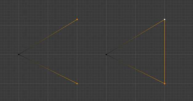
The two Vertices have been joined to form, in this case, a Closed Loop, Before on the Left, After on the Right.
Origen al cursor:
This button is used to set the Object Origin to the current Cursor location.
You can see a full list of available options in the table on the previous page
(Before You Begin) for both Edit and Object modes. Here the Working Plane
setting is irrelevant. This Tool works in Edit & Object Modes.
Selección: No se requiere ninguna en el modo de edición, seleccione un objeto en el modo de objeto.
Example 1: Set Object Origin to 1,3,2 in Edit Mode, set X, Y & Z inputs to 1,3,2 respectively,
set Operation to Cursor, click Absolute button to move cursor. Click Origin To Cursor Tool,
Origin is moved, but geometry is not moved from its absolute position in World Space.
Afinado:
This button is used to set the Object Origin to the current Cursor location.
You can see a full list of available options in the table on the previous page
(Before You Begin) for both Edit and Object modes. Here the Working Plane
setting is irrelevant. This Tool works only in Edit Mode.
Uses: Move/Rot Axis Selector.
Selection: Select vertices to be moved, then select fulcrum vertex with SHIFT+Mouse, active vertex is considered the rotational center.
Example 1: Taper the end of a cube in front view - 25 degrees,
set Angle to -25 degrees (25 degrees clockwise), select all vertices to be tapered,
SHIFT+Mouse select center of rotation point vertex, set Move/Rot selector to RotY,MovX,
set Working Plane to Front(X-Z), click Taper.
The significance of RotY,MovX is that the Y axis is used as the rotation axis
and vertices will be moved along the X axis, in View Working Plane Mode,
remember these are then Local axes, not Global ones.
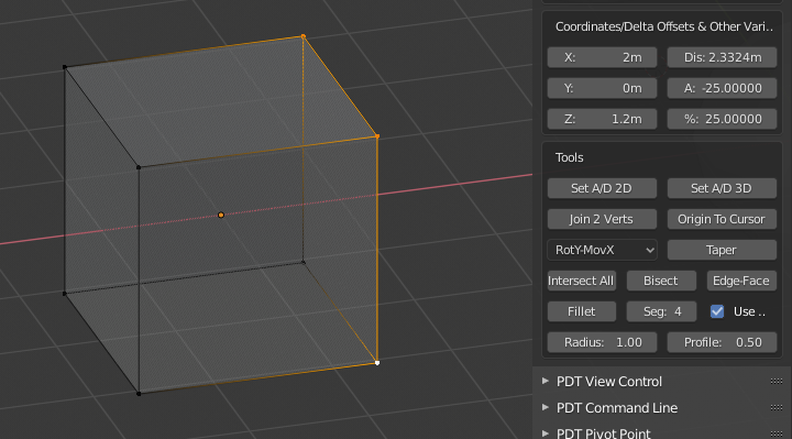
Antes, la cara está a 90 grados de la horizontal.
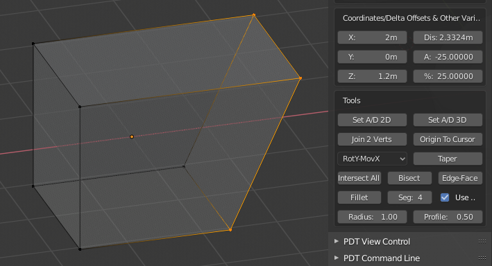
Después, la cara está ahora a 65 grados de la horizontal.
Intersectar todo:
Este botón será usado para cortar bordes en cualquier punto de intersección con otros bordes. Se podrá ver una lista completa de las opciones disponibles en la sección previa (Antes de comenzar), tanto para el modo Edición como para el modo Objeto. Aquí, la opción de Working Plane será irrelevante. Esta herramienta sólo funcionará en el modo Edición.
Selección: Seleccionar un conjunto de bordes por cualquier método.
Ejemplo 1: Cortar un conjunto de bordes en cada punto de intersección o intersectar, seleccionar los bordes requeridos, hacer clic en el botón Intersect All.
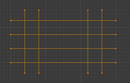
Bordes seleccionados antes.
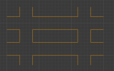
Bordes seleccionados después, algunos han sido removidos.
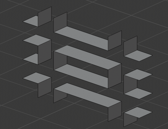
Bordes seleccionados, después de la extrusión.
Biseccionar (Cortar con plano):
Este botón será usado para formar un borde de bisección entre otros dos bordes coplanares. Se podrá ver una lista completa de las opciones disponibles en la sección previa (Antes de comenzar), tanto para el modo Edición como para el modo Objeto. Aquí, la opción de Working Plane será irrelevante. Esta herramienta sólo funcionará en el modo Edición.
Selección: Seleccionar dos bordes por cualquier método.
Ejemplo 1: Biseccionar dos bordes, seleccionar 2 bordes coplanares, hacer clic en el botón Cortar con plano.
Bordes biseccionados, a la izquierda Antes, a la derecha Después. Se puede apreciar cómo ambos bisectores han sido dibujados.
Borde a cara:
Este botón se utiliza para proyectar un borde hasta su intersección con una cara desconectada. Se puede ver una lista completa de opciones disponibles en la tabla de la página anterior (Antes de comenzar) para los modos Editar y Objeto. Aquí la configuración del Plano de trabajo es irrelevante. Esta herramienta sólo funciona en modo de edición.
Selección: Seleccionar solamente un borde y una cara desconectada.
El punto de intersección deberá estar dentro del área de la cara.
Ejemplo 1: Extender un borde hasta una cara desconectada, seleccionar un borde y una cara, hacer clic en el botón Edge-To-Face.
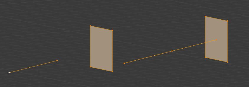
Borde extendido, a la izquierda Antes, a la derecha Después.
Fillet:
This button is used to fillet the corners of geometry, either closed edge loops, or edges.
You can see a full list of available options in the table on the previous page
(Before You Begin) for both Edit and Object modes. Here the Working Plane
setting is irrelevant. This Tool works only in Edit Mode.
Uses: Radius, Segments & Profile inputs & Use Vertices checkbox.
Selección: cualquier número de vértices, o bordes por cualquier método.
The Profile settings is the same as for Blender Bevel command, i.e. ranges from 0 to 1, 0.05 is a convex fillet, 0.5 is a concave fillet.
Example 1: Fillet a closed loop of edges at each corner radius 0.5, 6 segments,
profile 0.5, select corner vertices to be filleted, set Radius to 0.5,
set Segments to 6, set Profile to 0.5, check Use Vertices.
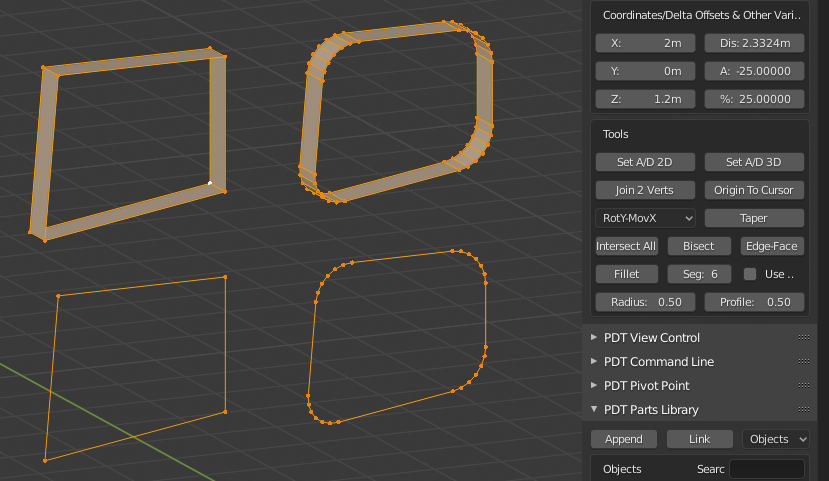
The image shows two Before and Afters, in the bottom set Use Vertices was checked, in the top set it was not, this is how to fillet edges.
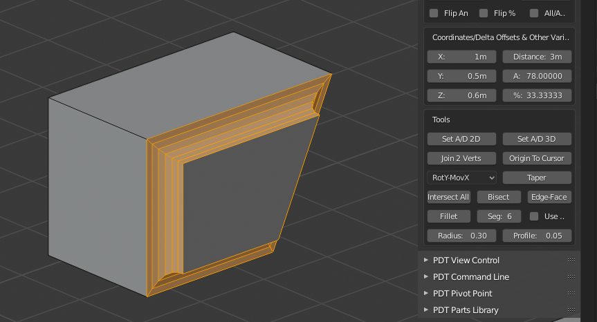
Another Before and After, you can see the settings used to produce this.
Tip! Using an even number of segments will result in better topology (no tris) where three bevels meet at 90 degree offsets, for example.
Note! From version 1.1.8 the Fillet Tool now has an Intersect checkbox.
When this is activated the toll will accept only two non-connected edges,
or four vertices representing two non-connected edges. These two edges and first intersected,
then the intersection vertex is filleted. The Use Verts
checkbox is ignored in this mode of operation. Should these two edges
not intersect in the Working Plane, an error is returned.
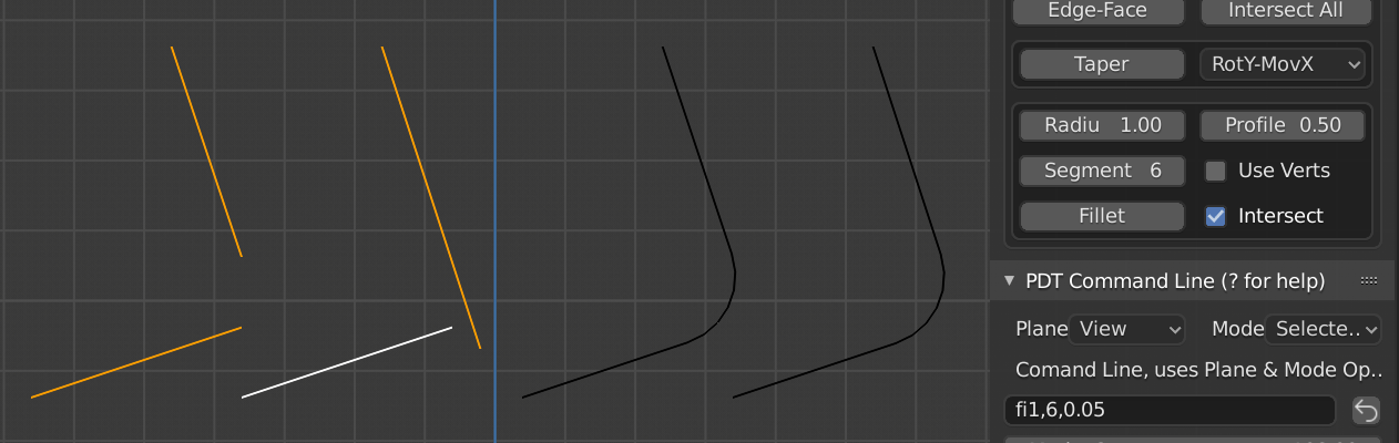
Two examples of Before on the Left and After on the Right.