Structure
Avec les maillages, tout est construit à partir de trois structures de base : vertices, edges et faces.

Exemple de structure de maillage.
Vertices (sommets)
The most elementary part of a mesh is the vertex (vertices plural) which is a single point or position in 3D space. Vertices are represented in the 3D Viewport in Edit Mode as small dots. The vertices of and object are stored as an array of coordinates.
Astuce
Do not mistake the object origin for a vertex. It may look similar, but it is bigger and cannot be selected.
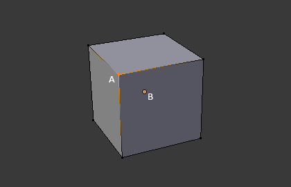
The vertex is labeled as « A »; the object’s origin dot is labeled as « B ».
Edges (arêtes)
An edge always connects two vertices by a straight line. The edges are the « wires » you see when you look at a mesh in wireframe view. They are usually invisible on the rendered image. They are used to construct faces.
Faces
Les faces sont utilisées pour construire la surface réelle de l’objet. Elles sont ce que vous voyez quand vous faites le rendu du maillage. Si cette zone ne contient pas de face, elle sera simplement transparente ou non existante dans l’image rendue.
Une face est définie par l’aire entre trois sommets (triangles), quatre sommets (quadrangles) ou plus de sommets (n-gons), avec une arête sur chaque côté. Les faces sont souvent abrégées en tris, quads et n-gons.
Les triangles sont toujours plats et donc faciles à calculer. D’un autre côté, les quadrangles « se déforment bien » et sont donc préférés pour l’animation et la modélisation par subdivision.
Normals
In geometry, a normal is a direction or line that is perpendicular to something, typically a triangle or surface but can also be relative to a line, a tangent line for a point on a curve, or a tangent plane for a point on a surface.
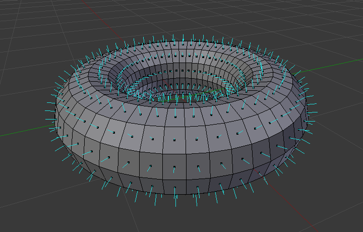
A visualization of the face normals of a torus.
In the figure above, each blue line represents the normal for a face on the torus. The lines are each perpendicular to the face on which they lie. The visualization can be activated, in Edit Mode, in the Mesh Display Viewport Overlays panel.
Properties
Reference
- Panel
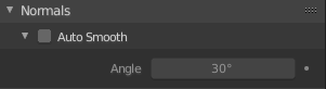
Normals panel.
- Auto Smooth
Edges where an angle between the faces is smaller than specified in the Angle button will be smoothed, when shading of these parts of the mesh is set to smooth. This is an easier way to combine smooth and sharp edges.
- Angle
Angle number field.
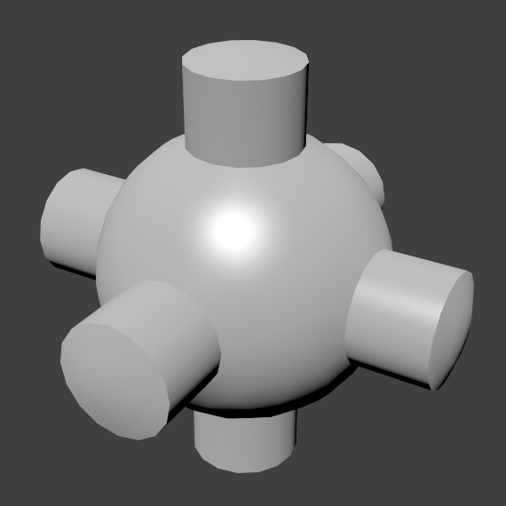
Example mesh with Auto Smooth enabled.
Advanced Smooth Shading & Sharp Edges
By default in Blender, with basic normal computing behavior, a sharp edge is always defined as an edge being either non-manifold, or having at least one of its faces defined as flat.
Enabling the Auto Smooth setting adds an extra parameter to define a sharp edge, the Angle threshold between two neighbor faces, above which the edge will always be considered as sharp.
Auto Smooth also enables Custom Split Normals handling, which can be either defined (and edited) as a mesh data layer, or generated on the fly by modifiers. In any case, when a mesh gets custom normals, they always supersede the default ones computed by Auto Smooth.
Sharp edges may still be used by the custom normals modifiers to compute their normals, depending on their settings.
Custom Split Normals
Custom Split Normals is a way to tweak/fake shading by pointing normals towards other directions than the default, auto-computed ones. It is mostly used in game development, where it helps counterbalance some issues generated by low-poly objects (the most common examples are low-poly trees, bushes, grass, etc. and the “rounded” corners).
Blender supports custom normals on a “smooth fan” base, defined as a set of neighbor face corners sharing the same vertex and “linked” by smooth edges. This means you can have normals per face corners, per a set of neighbor face corners, or per vertex.
Enabling Custom Split Normals
Reference
- Mode
Edit Mode
- Menu
Enables custom split normals.
Also, any of the custom normal editing tools (see below) will, as a convenience, enable custom normals if they are not already enabled.
Note
This has the side effect of enabling Auto Smooth, as that is necessary to use custom normals. Once you have custom normals, the angle threshold of the Auto Smooth behavior is disabled – all non-sharp-tagged edges will be considered as smooth, disregarding the angle between their faces.
Editing Custom Split Normals
Reference
- Mode
Edit Mode
- Menu
- Hotkey
Alt-N
There are a number of tools for editing custom split normals. The custom normal mesh edit tools can affect all normals (the default), or only selected ones. To select a custom normal associated with a particular vertex and face:
Make the element selection mode both Vertex and Face (use Shift-LMB to enable the second one).
Select one or more vertices, then select a face. This can be repeated to select more vertices and a different face and so on. It is easiest to see the effect of these tools if you turn on the Edit Mode Overlays option Display vertex-per-face normals as lines.
Voir aussi
Importing Custom Split Normals
Some tools, particularly those used in CAD, tend to generate irregular geometry when tessellating their objects into meshes (very thin and long triangles, etc.). Auto-computed normals on such geometry often gives bad artifacts, so it is important to be able to import and use the normals as generated by the CAD tool itself.
Note
Currently, only the FBX Importer and Alembic Importer are capable of importing custom normals.
Topology
Loops
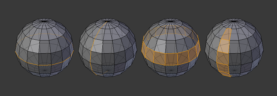
Edge et Face Loops.
Les Edge et Face Loops sont des ensembles de faces et d’arêtes qui forment des « boucles » continues comme affichées dans la Fig. Edge et Face Loops..
In the image above, loops that do not end in poles are cyclic (1 and 3). They start and end at the same vertex and divide the model into two partitions. Loops can be a quick and powerful tool to work with specific, continuous regions of a mesh and are a prerequisite for organic character animation. For a detailed description of how to work with loops in Blender, see: Edge Loop Selection.
Note
Notez que les loops (2 et 4) ne font pas le tour du modèle entier. Les loops s’arrêtent aux soi-disant pôles parce qu’il n’y a pas de façon unique de continuer un loop depuis un pôle. Les pôles sont des sommets qui sont connectés à trois, cinq ou plus d’arêtes. Par conséquent les sommets connectés à exactement un, deux ou quatre arêtes ne sont pas des pôles.
Edge Loops
Les loops (1 et 2) dans Fig. Edge et Face Loops. sont des Edge Loops. Ils connectent des sommets de sorte que chacun d’eux sur la loop ait exactement deux voisins qui ne sont pas sur la loop et placés des deux côtés de la loop (à l’exception des sommets de début et de fin dans le cas des pôles).
Les Edge Loops sont un concept particulièrement important dans la modélisation organique (subsurface) et l’animation de personnage. Correctement utilisées, elles vous permettent de construire avec relativement peu de sommets des modèles qui auront un aspect très naturel si elles sont utilisées comme surfaces de subdivision et qui se déforment très bien en animation.
Prenez comme exemple la Fig. Edge et Face Loops. de modélisation organique : les Edge Loops suivent les contours naturels et les lignes de déformation de la peau et des muscles sous-jacents et sont plus denses dans les zones qui se déforment davantage quand le personnage bouge, par exemple, au niveau des épaules et des genoux.
Des détails supplémentaires sur le travail avec les Edge Loops se trouvent dans Sélection d’Edge Loop.
Face Loops
Elles sont l’extension logique des Edge Loops du fait qu’elles sont composées de faces entre deux Edge Loops, comme affiché dans les loops (3 et 4) dans Fig. Edge et Face Loops.. Notez que pour les loops non circulaires (4) les faces contenant les pôles ne sont pas incluses dans une Face Loop.
Des détails supplémentaires sur le travail avec les Face Loops se trouvent dans Sélection de Face Loop.
Poles
See N-poles & E-poles.
Non-Manifold
See Non-manifold.