Flux de travail et exemples
Simple Drivers can be configured from the pop-over that appears when adding a new Driver.
Lors de l’ajout de plusieurs pilotes ou pour des configurations plus avancées, il est utile d’avoir ouvert le Drivers Editor.
Pilote de transformation
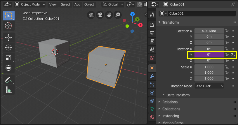
Contrôler une propriété avec la transformation d’un objet. Dans cet exemple, la rotation Y de Object 2 sera pilotée par la position X de Object 1.
À partir d’une installation simple avec deux objets :
Ajoutez un pilote à la propriété Rotation Y du second objet via le menu contextuel ou avec Ctrl-D.
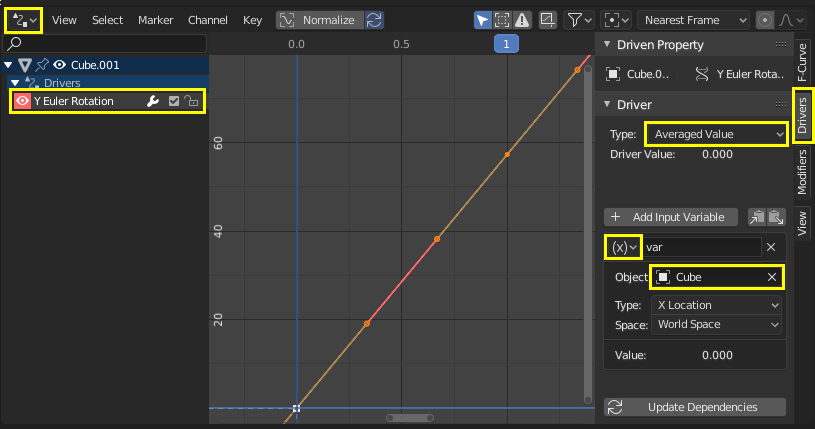
Ouvrez le Drivers Editor et sélectionnez la propriété Y Euler Rotation dans la région des canaux.
Ouvrez la région Sidebar et sélectionnez l’onglet Drivers.
Configurez le pilote pour qu’il soit à la Averaged Value d’un Transform Channel du premier objet.
Expérimentez le déplacement du premier objet et remarquez comment il affecte la rotation en Y du second objet.
Scripted Expression - Orbit a Point
Orbit an object’s position around a point with a custom Scripted Expression. The object’s position will change when scrubbing the timeline.
Using trigonometry, circular motion can be defined in 2D using the sinus and cosine functions. (See Unit Circle.)
Dans cet exemple, l’image actuelle est utilisée comme variable qui induit le mouvement. frame est une Simple Expression qui correspond à bpy.context.scene.frame_current.
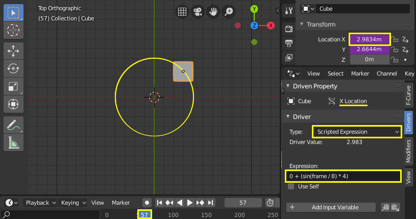
Ajoutez un pilote à la propriété X Location.
Réglez le Driver Type sur Scripted Expression.
Ajoutez l’expression
0 + (sin(frame / 8) * 4), où :frame/8: est la trame courante de l’animation, divisée par 8 pour ralentir l’orbite.(sin( )*4): multiplie le résultat desin(frame/8)par 4 pour obtenir un cercle plus grand.0 +: est utilisé pour contrôler le décalage par rapport au point central de l’orbite.
Ajoutez un pilote à la propriété Y Location avec l’expression « 0 + (cos(frame / 8) * 4)``.
Scrub the timeline to see the effect. Experiment with the variables to control the size and center of the orbit.
Custom Function - Square Value
Create a custom function to get the square of a value (i.e. value2). Adding the function to the Driver Namespace allows it to be used from driver expressions.
Le Driver Namespace possède une liste de fonctions intégrées à utiliser dans les expressions du pilote, ainsi que des constantes telles que π et e. Celles-ci peuvent être inspectées via la Console Python
>>> bpy.app.driver_namespace[' <tab>
                              acos']
                              acosh']
                              asin']
                              asinh']
                              atan']
                              ...
Pour ajouter une nouvelle fonction au Driver Namespace, la fonction elle-même doit être implémentée et ensuite ajoutée au bpy.app.driver_namespace.
Ajoutez ce qui suit à l’Éditeur de texte dans Blender et appuyez sur Run Script.
import bpy

def square(val):
   """Returns the square of the given value"""
   return val * val

# Add function to driver_namespace.
bpy.app.driver_namespace['square'] = square
Ajoutez un pilote avec une Scripted Expression telle que
square(frame).Observe the effect when scrubbing the timeline.
Il y a plus d’exemples de fonctions personnalisées disponibles dans l’Éiteur de texte de Blender .
Puisque Simple Expressions ne peut pas accéder aux fonctions personnalisées, leur utilisation n’a de sens que pour les calculs complexes.
Pilotes de forme clé
Improved Mesh Deformation
Fix intersection problems that happen when using armatures and weight painting, especially at joints. Shape keys can also be used to tweak and refine a rig, for example to suggest muscle formations. In this example, a shape key is used to improve the deformation at the elbow of a rudimentary arm.
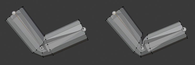
Left: Skeletal mesh deformation without correction. Right: Corrective shape key applied
- Setup
Add a mesh (in this example, a cylinder with loop cuts).
Ajoutez une armature avec une chaîne d’os.
Skin the mesh to the armature using weight painting.
(Note : pour parenter le maillage à l’armature : sélectionnez d’abord le maillage, puis l’armature et utilisez Ctrl-P pour parenter avec des poids automatiques).
Expérimentez la pose de l’armature et observez la déformation au niveau de l’articulation. Pour résoudre les problèmes d’intersection ou les angles qui semblent insatisfaisants, vous pouvez associer une Clé de forme à une pose.
- Clé de forme
Pose the armature such that the problems are visible. Be sure to cover the extreme poses that you want to support for the rig.
Avec le maillage sélectionné, ajoutez une nouvelle Shape Key en plus de la clé Basis.
Afin de créer la clé de forme au-dessus de la déformation de l’armature, activez à la fois Edit Mode Display et Cage Editing dans le modificateur Armature.
Entrez en Mode Édition et sélectionnez la nouvelle clé de forme dans le panneau properties. Ajustez les sommets comme vous le souhaitez. Sélectionnez la clé Basis pour basculer entre le maillage original et vos modifications. (Remarque : veillez à n’appliquer les modifications qu’à votre forme et non au maillage d’origine ou à d’autres clés existantes).
Once you are satisfied with how the deformation looks for the problematic pose, you’ll need to configure a driver to activate the shape smoothly when entering that position.
- Driver
Ajoutez un pilote à la Value de la clé de forme que vous avez créée.
Ouvrez l’éditeur Drivers et sélectionnez le pilote.
- Method 1 – Direct mapping to a bone rotation value
Une façon simple de configurer le pilote est d’établir une correspondance directe entre la valeur du canal de rotation d’un os et l’activation de la clé de forme Value. Cette méthode présente l’inconvénient de reposer sur un seul canal de rotation de l’os, ce qui peut être insuffisant pour exprimer précisément la condition dans laquelle la clé de forme doit être activée.
Dans l’onglet Drivers, sélectionnez la Averaged Value de la rotation de l’os que vous posez.
Comprenez l’axe de rotation qui vous intéresse en activant l’affichage des axes dans l’armature ou en observant les valeurs de transformation de l’os dans Properties.
Sélectionnez le canal de rotation et réglez-le sur local, c’est-à-dire la valeur de rotation de l’os par rapport à son os parent.
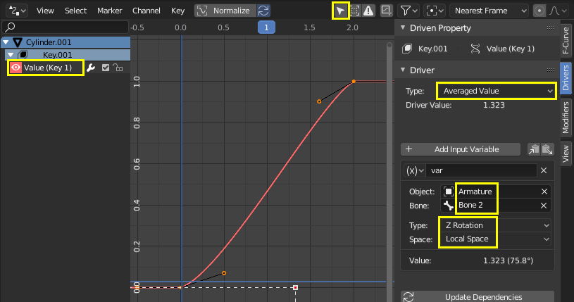
Définissez manuellement des points dans la courbe du pilote en sélectionnant une poignée et en la faisant glisser ou en insérant des valeurs dans l’onglet F-Curve. L’axe Y représente la clé de forme Value, qui doit aller de 0.0 à 1.0. L’axe X est généralement la trame, mais pour ce pilote, il représente la valeur de rotation en radians. Vous pouvez avoir plus de deux points dans la courbe et ajuster les transitions avec les poignées dans la vue de la courbe (G pour déplacer).
Pour vérifier que le pilote se comporte correctement, désélectionnez l’option permettant de n’afficher que les pilotes des objets sélectionnés. De cette façon, vous pouvez poser l’armature et garder un œil sur le pilote.
- Method 2 – Rotational difference to a target bone
This method requires an additional target or corrective bone, but it better expresses the spatial condition in 3D space of the bone that is causing the problem.
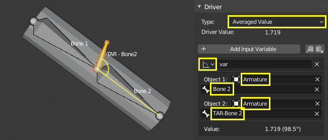
In armature Edit Mode, add a new bone extruded from Bone 1, in the position at which Bone 2 should have the shape key active. This type of bones usually follow a naming convention such as « TAR- » (target) or « COR- » (corrective).
In the Drivers tab, select the Averaged Value of the rotational difference between the bone you’re rotating and the target bone. A rotational difference is the minimum angle between two objects in World Space. It is therefore important that the bones have the same root, so that the only thing affecting the angle between the bones is the rotation of one of them. When the deformation bone (Bone 2) reaches the target rotation (TAR-Bone 2) the rotational difference will be 0°.
Manually adjust the driver curve handles so that the shape key Value (Y axis) is 1.0 when the rotational difference (X axis) is 0°. The Value should be 0.0 when the arm is extended, at which point the rotational difference should be around 90° or more (in radians).
See the steps in Method 1 on how to adjust the curve handles and confirm that the functionality is working. Pose the armature to verify that the ranges are correct.
Chained Relative Shape Keys
Activate different shape keys in succession. In this example, moving a single bone will activate first Key 1 and then Key 2. See also relative shape keys mix additively.
- Clés de forme
Add two shape keys to a mesh, besides the Basis.
Basis.¶ |
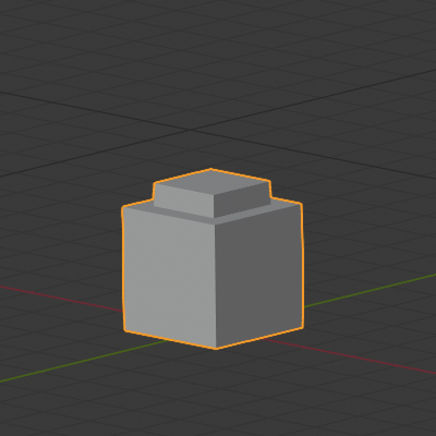
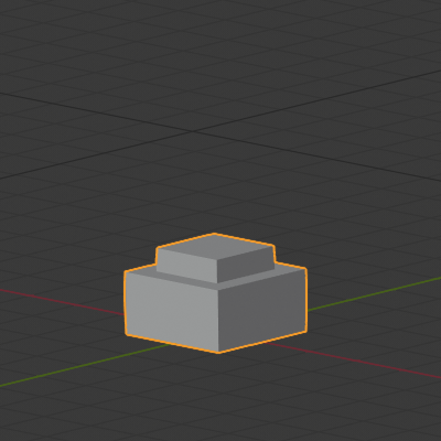
Key 1: top faces moved up by 1 m.¶ |
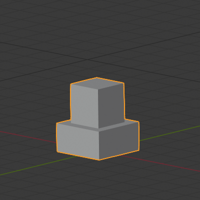
Key 2: inner top moved up by 1 m.¶ |
- Drivers
Add an armature with a single bone to control the shape keys. The goal is to activate the keys in succession as this bone moves up.
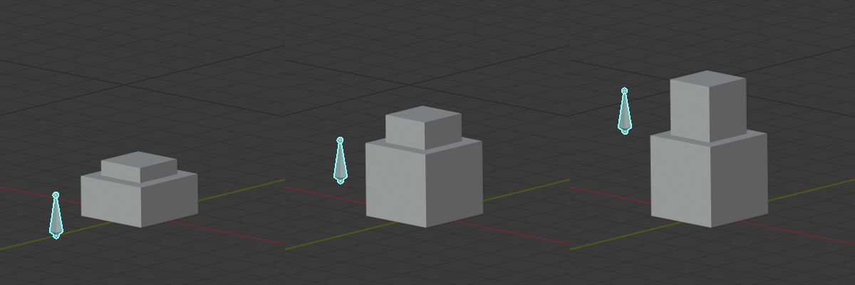
As shown in the picture above, when the bone is halfway up, both Key 1 and Key 2 have an influence. It is a matter of preference if Key 1 should be at its maximum Value before Key 2 starts to become active, or how much they should overlap. This example shows a seamless blend.
For a seamless blend where there is overlap, Key 1 should have a Value of 0.0 when the bone is at the bottom and increase linearly to 1.0 until the bone is past the midpoint height. Key 2 should have a value of 0.0 before the midpoint height and then increase at the same rate than Key 1 until reaching Value 1.0 when the bone is at maximum height.
Add a driver to the Value of Key 1 and Key 2. In the Drivers tab, configure both drivers to be the Averaged Value of a variable with the bone’s Z location.
Determine the range of the bone’s motion in the World Z axis by moving it up so that it is aligned with the top of the mesh when both keys are active. Here we will use [0.0 , 2.5].
Configure the driver functions so that the Value of the shape keys (Y axis) is as desired for the bone’s height (X axis).
The driver functions should be linear, therefore, they can be defined analytically with a function of type \(y = a + bx\), where \(a\) is an offset in \(y\) and \(b\) is the slope.
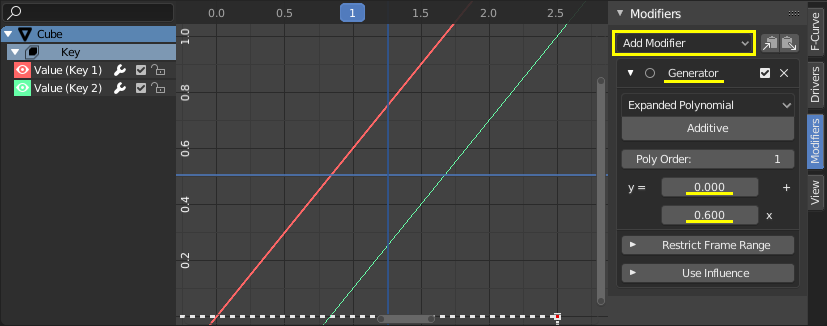
In the Modifiers tab, add a Generator of type Extended Polynomial for both drivers.
Play with the values of \(a\) and \(b\) so that the curves go from [0.0 , 1.0] in the Y axis and from [0.0 , 2.5] in the X axis. The curves should overlap in the mid area of the X axis and they should have the same slope (\(b\)).
Possible values are Key 1: \(y = 0.0 + 0.6x\) and Key 2: \(y = -0.5 + 0.6x\).
Note that the functions go outside the range [0.0 , 1.0] for the shape keys” Value, but that has no effect because Value is clamped in a Range in the Shape Keys panel.