構造
メッシュでは、全てが3つの基本的な構造、すなわち 頂点 、辺、 面 から成ります。

メッシュ構造の例
頂点
The most elementary part of a mesh is the vertex (vertices plural) which is a single point or position in 3D space. Vertices are represented in the 3D Viewport in Edit Mode as small dots. The vertices of and object are stored as an array of coordinates.
ちなみに
Do not mistake the object origin for a vertex. It may look similar, but it is bigger and cannot be selected.
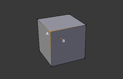
The vertex is labeled as "A"; the object's origin dot is labeled as "B".
辺
An edge always connects two vertices by a straight line. The edges are the "wires" you see when you look at a mesh in wireframe view. They are usually invisible on the rendered image. They are used to construct faces.
面
面はオブジェクトの実際の表面を作るために使われます。メッシュのレンダリングの結果として見えるのはこの面です。その領域が面を持っていない場合は、レンダリング結果では透明もしくは存在しない物として出力されます。
1つの面は3つ(三角形、triangles)、4つ(四角形、quadrangles)、それ以上の数(nゴン、n-gons)の頂点の間にあり、辺で囲まれた領域として定義されます。それぞれの面はよく、 tris、quads、そしてn-gons として省略されます。
三角形は常に平面であり、簡単に計算ができます。一方、四角形は"うまく変形する"ため、アニメーションやサブディビジョン・モデリングで好まれて使われます。
Normals
In geometry, a normal is a direction or line that is perpendicular to something, typically a triangle or surface but can also be relative to a line, a tangent line for a point on a curve, or a tangent plane for a point on a surface.
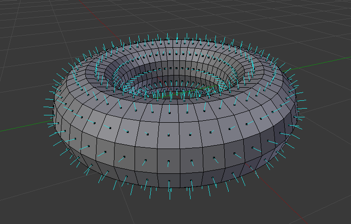
A visualization of the face normals of a torus.
In the figure above, each blue line represents the normal for a face on the torus. The lines are each perpendicular to the face on which they lie. The visualization can be activated, in Edit Mode, in the Mesh Display Viewport Overlays panel.
Properties
Reference
| Panel: |
|---|
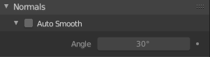
Normals panel.
- Auto Smooth
Edges where an angle between the faces is smaller than specified in the Angle button will be smoothed, when shading of these parts of the mesh is set to smooth. This is an easier way to combine smooth and sharp edges.
- Angle
- Angle number field.
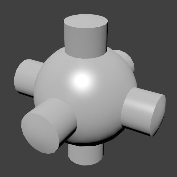
Example mesh with Auto Smooth enabled.
Custom Split Normals
Custom Split Normals is a way to tweak/fake shading by pointing normals towards other directions than the default, auto-computed ones. It is mostly used in game development, where it helps counterbalance some issues generated by low-poly objects (the most common examples are low-poly trees, bushes, grass, etc. and the 'rounded' corners).
Blender supports custom normals on a 'smooth fan' base, defined as a set of neighbor face corners sharing the same vertex and 'linked' by smooth edges. This means you can have normals per face corners, per a set of neighbor face corners, or per vertex.
Enabling Custom Split Normals
Reference
| Mode: | Edit Mode |
|---|---|
| Menu: |
Enables Custom Split Normals.
Also, any of the custom normal editing tools (see below) will, as a convenience, enable custom normals if they are not already enabled.
注釈
This has the side effect of enabling Auto Smooth, as that is necessary to use custom normals. Once you have custom normals, the angle threshold of the Auto Smooth behavior is disabled -- all non-sharp-tagged edges will be considered as smooth, disregarding the angle between their faces.
Editing Custom Split Normals
Reference
| Mode: | Edit Mode |
|---|---|
| Menu: | |
| Hotkey: | Alt-N |
There are a number of tools for editing custom split normals. The custom normal mesh edit tools can affect all normals (the default), or only selected ones. To select a custom normal associated with a particular vertex and face:
- Make the element selection mode both Vertex and Face (use Shift-LMB to enable the second one).
- Select one or more vertices, then select a face. This can be repeated to select more vertices and a different face and so on. It is easiest to see the effect of these tools if you turn on the Edit Mode Overlays option Display vertex-per-face normals as lines.
参考
Importing Custom Split Normals
Some tools, particularly those used in CAD, tend to generate irregular geometry when tessellating their objects into meshes (very thin and long triangles, etc.). Auto-computed normals on such geometry often gives bad artifacts, so it is important to be able to import and use the normals as generated by the CAD tool itself.
注釈
Currently, only the FBX Importer and Alembic Importer are capable of importing custom normals.
Topology
ループ
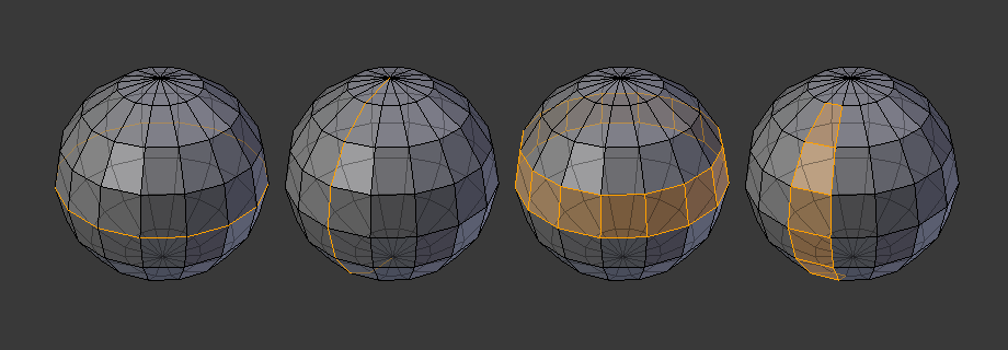
辺と面のループ
辺 と 面 のループは図 辺と面のループ で示すように連続した「ループ」を成す面や辺の集まりです。
In the image above, loops that do not end in poles are cyclic (1 and 3). They start and end at the same vertex and divide the model into two partitions. Loops can be a quick and powerful tool to work with specific, continuous regions of a mesh and are a prerequisite for organic character animation. For a detailed description of how to work with loops in Blender, see: Edge Loop Selection.
注釈
2と4で示したループがモデル全体を回らないことに注意してください。ループはポール(poles)と呼ばれるところで止まり、これはポール以降はループを一意に続ける方法がないからです。ポールは3つ、5つ、あるいはそれ以上の数の辺と繋がった頂点です。したがって、1つ、2つ、あるいは4つの辺と繋がった頂点はポールではありません。
辺ループ
図 辺と面のループ において、1と2で示したループは辺ループです。辺ループは頂点を繋げ、ループ上の各頂点において、ループ上にない2つの頂点に隣接し、その2つの頂点がループの両側に配置されるようにしています。(ポールがある場合の始点と終点は例外です)
有機的な(サブサーフェスを使った)モデリングやキャラクターでは、辺ループは特に重要な概念です。適切に使えば、サブディビジョンサーフェスで使うととても自然に見えるモデルを比較的少数の頂点で作れますし、アニメーションにおいても綺麗に変形します。
例として図 辺と面のループ を有機モデリングとして捉えてみましょう。辺ループは皮膚やその下の筋肉の自然な輪郭や変形の線に沿って走り、キャラクターが動く時により大きく変形するところ(例えば、肩や膝など)では密度がより高くなります。
より詳細な辺ループの扱い方は 辺ループ選択 を参照してください。
面ループ
面ループは辺ループの理論的な拡張であり、図 辺と面のループ の3と4で示すように2つの辺ループの間の面から成ります。4で示すように、循環しないループではポールを含む面は面ループに含まれないことに注意してください。
より詳細な面ループの扱い方は 面ループ選択 を参照してください。
Poles
See N-poles & E-poles.
Non-Manifold
See Non-manifold.