UV Tools
参照
- Editor(エディター)
3D Viewport(3Dビューポート)
- Mode(モード)
Edit Mode(編集モード)
- Menu(メニュー)
- ショートカットキー
U
BlenderはUVをマッピングするいくつかの方法を提供します。より単純な投影方法では、サーフェスを介して点/軸/平面に向かって点の位置を補間することにより、3D空間を2D空間にマッピングする式を使用します。より高度な方法は、より複雑なモデルで使用でき、より明確な用途があります。
Unwrap(展開)
参照
- Editor(エディター)
3D Viewport(3Dビューポート) と UV Editor(UVエディター)
- Mode(モード)
Edit Mode(編集モード)
- Menu(メニュー)
- ショートカットキー
U
Seam(シーム) に沿ってカットすることにより、メッシュ表面を平らにします。有機的な形に役立ちます。
注釈
The Unwrap operator is the only UV unwrapping operator that takes into account seams.
Begin by selecting all faces you want to unwrap. In the 3D Viewport, select or U and select Unwrap. You can also do this from the UV Editor with or U. This method will unwrap all faces and reset previous work. The UVs menu will appear in the UV Editor after unwrapping has been performed once.
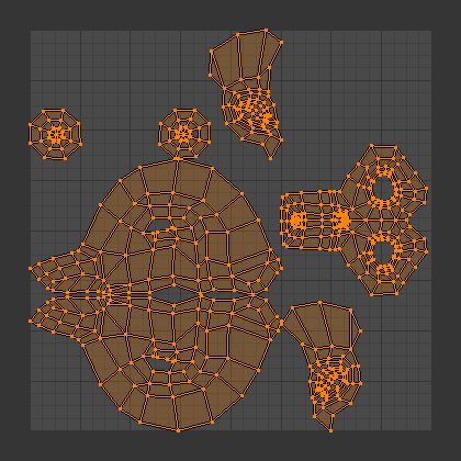
スザンヌをUnwrap(展開)した結果。
This tool unwraps the faces of the object to provide the "best fit" scenario based on how the faces are connected and will fit within the image, and takes into account any seams within the selected faces. If possible, each selected face gets its own different area of the image and is not overlapping any other faces UVs. If all faces of an object are selected, then each face is mapped to a part of the image.
Options(オプション)
Blender has two ways of calculating the unwrapping. They can be selected in the tool setting in the tool panel in the 3D Viewport.
- Angle Based(アングルベース)
This method gives a good 2D representation of a mesh.
- Conformal(等角)
Uses LSCM (Least Squares Conformal Mapping). This usually gives a less accurate UV mapping than Angle Based, but works better for simpler objects.
- Fill Holes(穴をフィル)
Fill Holes(穴をフィル) をアクティブにすると、オーバーラップが発生するのを防ぎ、UV領域のホールをより適切に表すことができます。
- Correct Aspect(アスペクト比の補正)
Map UVs taking image aspect into account.
- Use Subdivision Surface Modifier
Subdivision Surface(サブディビジョンサーフェス)モディファイアー後の頂点位置を考慮してUVをマッピングします。
- Margin(余白)
Space between UV islands.
Tip
面のUV画像テクスチャは、画像 全体 ではなく、画像の 一部 のみを使用する必要があります。また、同じ画像の一部を複数の面で共有することもできます。面は、画像全体のより少なくマッピングすることができます。
Smart UV Project(スマートUV投影)
参照
- Editor(エディター)
3D Viewport(3Dビューポート)
- Mode(モード)
Edit Mode(編集モード)
- Menu(メニュー)
- ショートカットキー
U
Smart UV Project, cuts the mesh based on an angle threshold (angular changes in your mesh). This gives you fine control over how automatic seams are be created. It is good method for simple and complex geometric forms, such as mechanical objects or architecture.
This algorithm examines the shape of your object, the faces selected and their relation to one another, and creates a UV map based on this information and settings that you supply.
下の例では、Smart Mapperは、立方体のすべての面を、立方体の面と同じように、立方体の6つの面すべてが直角に収まるように、上に3つの側面、下に3つの側面のすっきりとした配置にマッピングしました。
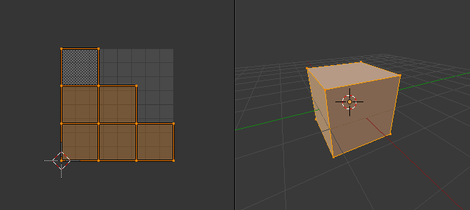
立方体のSmart UV Project(スマートUV投影)。
For more complex mechanical objects, this tool can quickly and easily create a regular and straightforward UV layout for you.
Options(オプション)
The Adjust Last Operation(最後の操作を調整) panel allows fine control over how the mesh is unwrapped:
- Angle Limit(角度制限)
これにより、面のグループ化方法が制御できます: 制限を高くすると、多くの小さなグループになりますが、歪みは少なくなります。制限を低くすると、作成されるグループが少なくなり、歪みが大きくなります。
- Island Margin(アイランドの余白)
This controls how closely the UV islands are packed together. A higher number will add more space between islands.
- Area Weight(面積ウェイト)
より大きな領域を持つ面による重み投影のベクトル。
Lightmap Pack(ライトマップパック)
参照
- Editor(エディター)
3D Viewport(3Dビューポート)
- Mode(モード)
Edit Mode(編集モード)
- Menu(メニュー)
- ショートカットキー
U
Lightmap Pack takes each of a mesh's faces, or selected faces, and packs them into the UV bounds. Lightmaps are used primarily in realtime rendering, where lighting information is baked onto texture maps, when it is needed to use as much UV space as possible. It can also work on several meshes at once. It has several options that appear in the Toolbar:
You can set the tool to map just Selected Faces or All Faces if working with a single mesh.
The Selected Mesh Object option works on multiple meshes. To use this, in Object Mode select several mesh objects, then go into Edit Mode and activate the tool.
Options(オプション)
- Share Texture Space(テクスチャ空間を共有)
これは、複数のメッシュをマッピングする場合に役立ちます。オーバーラップすることなく、すべてのオブジェクトの面をUV境界に合わせようとします。
- New UV Map(新規UVマップ)
複数のメッシュをマッピングする場合、このオプションはメッシュごとに新しいUVマップを作成します。 UV Maps(UVマップ) を参照してください。
- New Image
Assigns new images for every mesh, but only one if Shared Tex Space is enabled.
- Image Size(画像のサイズ)
Set the size of the new image.
- Pack Quality(梱包の品質)
複雑な箱詰めを行う前に準備を行います。
- Margin(余白)
This controls how closely the UV islands are packed together. A higher number will add more space between islands.
Follow Active Quads(アクティブ四角形面に追従)
参照
- Editor(エディター)
3D Viewport(3Dビューポート)
- Mode(モード)
Edit Mode(編集モード)
- Menu(メニュー)
- ショートカットキー
U
The Follow Active Quads tool takes the selected faces and lays them out by following continuous face loops, even if the mesh face is irregularly-shaped. Note that it does not respect the image size, so you may have to scale them all down a bit to fit the image area.
Options(オプション)
- Edge Length Mode(辺の長さモード)
- Even(均一)
Space all UVs evenly.
- Length(長さ)
(未稿)。
- Length Average(長さの平均)
各ループのUV辺の長さの平均スペース。
注釈
Please note that it is the shape of the active quad in UV space that is being followed, not its shape in 3D space. To get a clean 90-degree unwrap make sure the active quad is a rectangle in UV space before using "Follow active quad".
Cube Projection(キューブ投影)
参照
- Editor(エディター)
3D Viewport(3Dビューポート)
- Mode(モード)
Edit Mode(編集モード)
- Menu(メニュー)
- ショートカットキー
U
Cube Projection(キューブ投影)は、メッシュを立方体の面にマッピングし、次に展開します。メッシュを6つの別々の平面に投影し、6つのUVアイランドを作成します。UVエディタでは、これらは重なって表示されますが、移動できます。 Editing UVs を参照してください。
Options(オプション)
- Cube Size(立方体サイズ)
投影する立方体のサイズを設定します。
共通
The following settings are common for the Cube, Cylinder, and Sphere mappings:
- Correct Aspect(アスペクト比の補正)
Map UVs will take the images aspect ratio into consideration. If an image has already been mapped to the Texture Space that is non-square, the projection will take this into account and distort the mapping to appear correct.
- Clip to Bounds(境界でクリッピング)
(0から1)の範囲外にあるUVは、最も近いUV 空間の境界に移動することにより、その範囲にクリップされます。
- Scale to Bounds(境界に拡大縮小)
UVマップが(0から1)の範囲よりも大きい場合、マップ全体が内側に収まるように拡大縮小されます。
Cylinder Projection(円筒状投影)
参照
- Editor(エディター)
3D Viewport(3Dビューポート)
- Mode(モード)
Edit Mode(編集モード)
- Menu(メニュー)
- ショートカットキー
U
通常、円筒(チューブ)を縦にスリットして平らに折りたたむように展開するには、Blenderは、チューブが "上" に立った状態で、ビューを垂直にする必要があります。ビューが異なれば、チューブのUVマップへの投影も異なり、使用すると画像が歪んでしまいます。ただし、計算を行う軸は手動で設定できます。
Options(オプション)
- Direction(方向)
- View on Poles(ビューを極に)
ビューから真下にある軸を使用して、上から(極で)表示する場合に使用します。
- View on Equator(ビューを赤道に)
ビューが垂直軸を使用して赤道を見ている場合に使用します。
- Align to Object(オブジェクトで揃える)
オブジェクトの変換を使用して軸を計算します。
- Align(整列)
上向きの軸を選択します。
- Polar ZX(極のZX)
極 0はX軸上にあります。
- Polar ZY(極のZY)
極 0はY軸上にあります。
- Radius(半径)
使用する円柱の半径。
Sphere Projection(球状投影)
参照
- Editor(エディター)
3D Viewport(3Dビューポート)
- Mode(モード)
Edit Mode(編集モード)
- Menu(メニュー)
- ショートカットキー
U
Spherical mappings is similar to cylinder but the difference is that a cylindrical mapping projects the UVs on a plane toward the cylinder shape, while a spherical map takes into account the sphere's curvature, and each latitude line becomes evenly spaced. Sphere Projection is useful for spherical shapes, like eyes, planets, etc.
世界をマッピングするための最初のカートグラファーのアプローチを思い出してください。さまざまな観点から球を展開するときに、ここで同じことを達成できます。通常、球を展開するには、上部と下部に極がある球を表示します。展開後、Blenderは正距円筒図法を提供します。あなたに面している赤道上の点は、画像の中央になります。極座標ビューでは、非常に異なるが一般的な投影マップが得られます。地球の正距円筒図法をUV画像として使用すると、球体への優れた惑星マッピングが得られます。
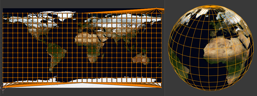
Sphere Projection(球状投影)で正距円筒図法を使用します。
Options(オプション)
- Direction(方向)
- View on Poles(ビューを極に)
ビューから真下にある軸を使用して、上から(極で)表示する場合に使用します。
- View on Equator(ビューを赤道に)
ビューが垂直軸を使用して赤道を見ている場合に使用します。
- Align to Object(オブジェクトで揃える)
オブジェクトの変換を使用して軸を計算します。
- Align(整列)
上向きの軸を選択します。
- Polar ZX(極のZX)
極 0はX軸上にあります。
- Polar ZY(極のZY)
極 0はY軸上にあります。
- Radius(半径)
The radius of the sphere to use.
Project from View(ビューから投影)
参照
- Editor(エディター)
3D Viewport(3Dビューポート)
- Mode(モード)
Edit Mode(編集モード)
- Menu(メニュー)
- ショートカットキー
U
Project from View(ビューから投影) は、3D Viewport(3Dビューポート)の現在のビューを取得し、表示されているとおりにメッシュを平坦化します。モデル化したオブジェクトのUVテクスチャとしてオブジェクトのリアル画像を使用している場合は、このオプションを使用します。モデルがあなたから遠ざかる領域でストレッチします。
Options(オプション)
See also Common options.
- Orthographic(平行投影)
平行投影を適用します。
Project from View (Bounds)(ビューから投影 (バウンド))
参照
- Editor(エディター)
3D Viewport(3Dビューポート)
- Mode(モード)
Edit Mode(編集モード)
- Menu(メニュー)
- ショートカットキー
U
Similar to Project from View, but with Scale to Bounds and Correct Aspect activated.
Reset(リセット)
参照
- Editor(エディター)
3D Viewport(3Dビューポート) と UV Editor(UVエディター)
- Mode(モード)
Edit Mode(編集モード)
- Menu(メニュー)
- ショートカットキー
U
UVをリセットは、各面をUVグリッドに合わせてマッピングし、各面に同じマッピングを提供します。
タイル化可能な画像を使用する場合は、その画像の滑らかな繰り返しで表面が覆われ、個々の面の形状に合わせて画像が傾斜します。この展開オプションを使用して、マップをリセットし、展開を元に戻します(最初に戻ります)。