Structure
Com malhas, tudo é construído a partir de três estruturas básicas: vértices, arestas e faces.

Exemplo de estrutura de malha.
Vértices
The most elementary part of a mesh is the vertex (vertices plural) which is a single point or position in 3D space. Vertices are represented in the 3D Viewport in Edit Mode as small dots. The vertices of an object are stored as an array of coordinates.
Dica
Do not mistake the object origin for a vertex. It may look similar, but it is bigger and cannot be selected.
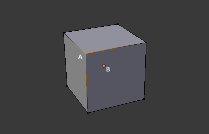
The vertex is labeled as «A»; the object’s origin dot is labeled as «B».
Arestas
An edge always connects two vertices by a straight line. The edges are the «wires» you see when you look at a mesh in wireframe view. They are usually invisible on the rendered image. They are used to construct faces.
Faces
Faces are used to build the actual surface of the object. They are what you see when you render the mesh. If this area does not contain a face, it will simply be transparent or nonexistent in the rendered image.
Uma face é definida como uma área entre tanto três (triângulos), quatro (quadriláteros) ou mais (multiláteros ou «n-gons») vértices , com uma aresta em cada lado. As faces são muitas vezes abreviadas a tris, quads & n-gons.
Triângulos são sempre planos e portanto fáceis de calcular. Por outro lado, quadrados deformam bem e são portanto preferidos para animação e modelagem por subdivisão.
Normais
In geometry, a normal is a direction or line that is perpendicular to something, typically a triangle or surface but can also be relative to a line, a tangent line for a point on a curve, or a tangent plane for a point on a surface.
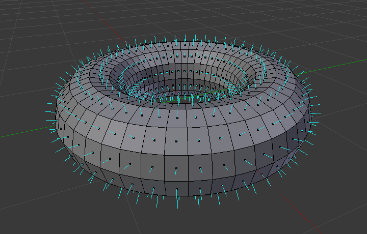
A visualization of the face normals of a torus.
In the figure above, each blue line represents the normal for a face on the torus. The lines are each perpendicular to the face on which they lie. The visualization can be activated, in Edit Mode, in the Mesh Display Viewport Overlays panel.
Properties
Reference
- Panel
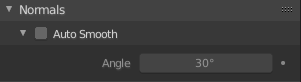
O painel das normais.
- Suavizar automaticamente
Edges where an angle between the faces is smaller than specified in the Angle field will be smoothed, when shading of these parts of the mesh is set to smooth. This is an easier way to combine smooth and sharp edges.
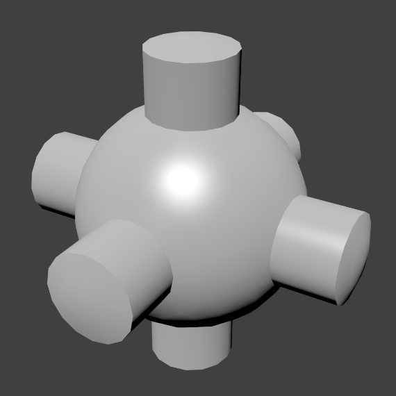
Malha de exemplo com a opção Suavizar automaticamente habilitada.
Advanced Smooth Shading & Sharp Edges
By default in Blender, with basic normal computing behavior, a sharp edge is always defined as an edge being either non-manifold, or having at least one of its faces defined as flat.
Enabling the Auto Smooth setting adds an extra parameter to define a sharp edge, the Angle threshold between two neighbor faces, above which the edge will always be considered as sharp.
Auto Smooth also enables Custom Split Normals handling, which can be either defined (and edited) as a mesh data layer, or generated on the fly by modifiers. In any case, when a mesh gets custom normals, they always supersede the default ones computed by Auto Smooth.
Sharp edges may still be used by the custom normals modifiers to compute their normals, depending on their settings.
Custom Split Normals
Custom Split Normals is a way to tweak/fake shading by pointing normals towards other directions than the default, auto-computed ones. It is mostly used in game development, where it helps counterbalance some issues generated by low-poly objects (the most common examples are low-poly trees, bushes, grass, etc. and the “rounded” corners).
Blender supports custom normals on a “smooth fan” base, defined as a set of neighbor face corners sharing the same vertex and “linked” by smooth edges. This means you can have normals per face corners, per a set of neighbor face corners, or per vertex.
Enabling Custom Split Normals
Reference
- Mode
Edit Mode
- Menu
Enables custom split normals. Also, any of the custom normal editing tools (see below) will, as a convenience, enable custom normals if they are not already enabled.
Nota
This has the side effect of enabling Auto Smooth, as that is necessary to use custom normals. Once you have custom normals, the angle threshold of the Auto Smooth behavior is disabled – all non-sharp-tagged edges will be considered as smooth, disregarding the angle between their faces.
Editing Custom Split Normals
Reference
- Mode
Edit Mode
- Menu
Painel:
- Atalho
Alt-N
There are a number of tools for editing custom split normals. The custom normal mesh edit tools can affect all normals (the default), or only selected ones. To select a custom normal associated with a particular vertex and face:
Make the element selection mode both Vertex and Face (use Shift-LMB to enable the second one).
Select one or more vertices, then select a face. This can be repeated to select more vertices and a different face and so on. It is easiest to see the effect of these tools if you turn on the Edit Mode Overlays option Display vertex-per-face normals as lines.
Veja também
Importing Custom Split Normals
Some tools, particularly those used in CAD, tend to generate irregular geometry when tessellating their objects into meshes (very thin and long triangles, etc.). Auto-computed normals on such geometry often gives bad artifacts, so it is important to be able to import and use the normals as generated by the CAD tool itself.
Nota
Currently, only the FBX Importer and Alembic Importer are capable of importing custom normals.
Topologia
Anéis
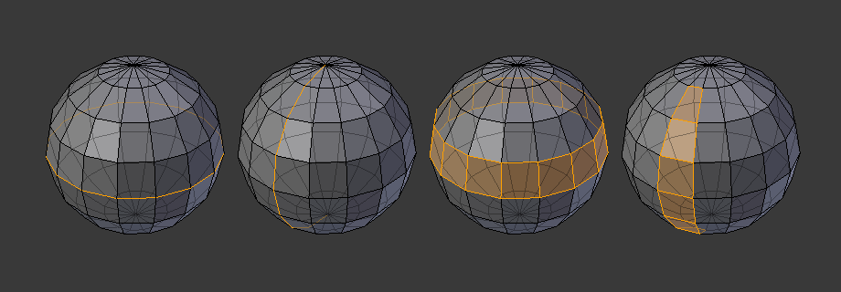
Anéis de arestas e faces.
Os anéis de arestas e faces sã conjuntos de arestas e faces que formam «anéis» contínuos como mostrados na Fig. Anéis de arestas e faces..
In the image above, loops that do not end in poles are cyclic (1 and 3). They start and end at the same vertex and divide the model into two partitions. Loops can be a quick and powerful tool to work with specific, continuous regions of a mesh and are a prerequisite for organic character animation. For a detailed description of how to work with loops in Blender, see: Select Edge Loops.
Nota
Note que os anéis (2 e 4) não dão a volta completa em torno de todo o modelo. Os anéis param nos chamados polos pois não há uma única maneira de continuar um anel a partir de um polo. Os polos são vértices que estão conectados a três, cinco ou mais arestas. Da mesma maneira, vértices conectados a exatamente uma, duas ou quatro arestas não sã polos.
Anéis de arestas
Os anéis (1 e 2) na Fig. Anéis de arestas e faces. são anéis de arestas. Eles conectam vértices de maneira que cada um dos que estão no anel tenha exatamente dois vizinhos que não estão no anel e que estão posicionados em ambos os lados do anel (exceto os vértices inicial e final, no caso dos polos).
Os anéis de aresta são um conceito importante, especialmente em modelagem de orgânicos (com subdivisão de superfícies) e animação de personagens. Quando usados de maneira correta, eles permitem que você construa modelos com relativamente poucos vértices que parecem bastante naturais quando usados como superfícies de subdivisão e que são deformados muito bem durante as animações.
Take Fig. Anéis de arestas e faces. in organic modeling as an example: the edge loops follow the natural contours and deformation lines of the skin and the underlying muscles. The loops are denser in areas that deform more when the character moves, for example at the shoulders or knees.
Further details on working with edge loops can be found in Select Edge Loops.
Anéis de faces
Estes são uma extensão lógica dos anéis de arestas já que estes consistem nas faces entre dois anéis de arestas, como mostrado nos anéis (3 e 4) na Fig. Anéis de arestas e faces.. Note que para anéis não circulares (4) as faces que contém os polos não são incluídas no anel de faces.
Detalhes adicionais sobre como trabalhar com os anéis de faces podem ser encontrados em Seleção de Anéis de Faces.
Poles
See N-poles & E-poles.
Non-Manifold
See Non-manifold.