Knife Topology Tool
Referência
- Mode:
Edit Mode
- Tool:
- Menu:
- Atalho:
K
The Knife tool can be used to interactively subdivide (cut up) geometry by drawing lines or closed loops to create holes.
Uso
When using Knife, the cursor changes to an icon of a scalpel and the header changes to display options for the tool. You can draw connected straight lines by clicking LMB, marked with small green squares. Red squares are already defined cuts. Surrounding red squares mean that there is a cut already in that position, so no additional vertex will be created (besides the first one).
If multiple objects are selected before entering Edit Mode, then knife cuts will affect all of those objects.
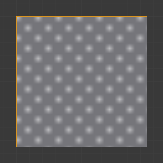
Mesh before knife cut. |
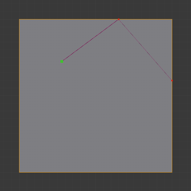
Knife cut active. |
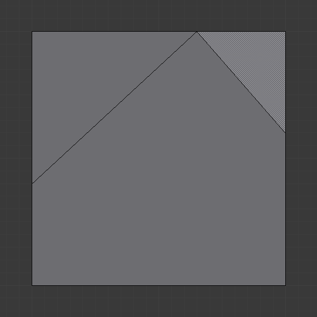
After confirming knife cut. |
Tool Settings
- Occlude Geometry
Only cut geometry visible on screen.
- Only Selected Shift-K
Only cuts through selected geometry.
- Raio-X
Show cut points on non-visible geometry too, when Occlude Geometry is deactivated.
- Measurement
Which visible measurements to show.
Distance, Angle, None, Both
- Angle Snapping
Whether or not dragged lines should be constrained to particular angles, and if so, which coordinate system the angle is relative to.
None, Screen, Relative
- Angle Snapping Increment
When angle snapping is on, the angle will be constrained to a multiple of this angle.
Controles
- Confirm Spacebar or Return
Confirms the cut. Return will leave selected every edge except the new edges created from the cut.
- Cancel Esc
Cancels the cut.
- Draw a Continuous Line LMB drag.
So you can draw a free-hand line over a surface, points will be created at edge intersections.
- Close Loop double-click LMB
This is a quick way to close the loop you are currently cutting.
- New Cut RMB
Begins a new cut. This allows you to define multiple distinct cut lines. If multiple cuts have been defined, they are recognized as new snapping points.
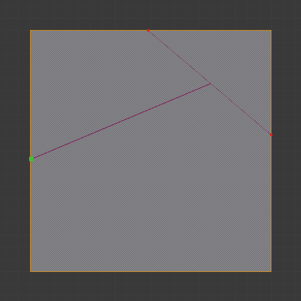
Creating multiple cuts.
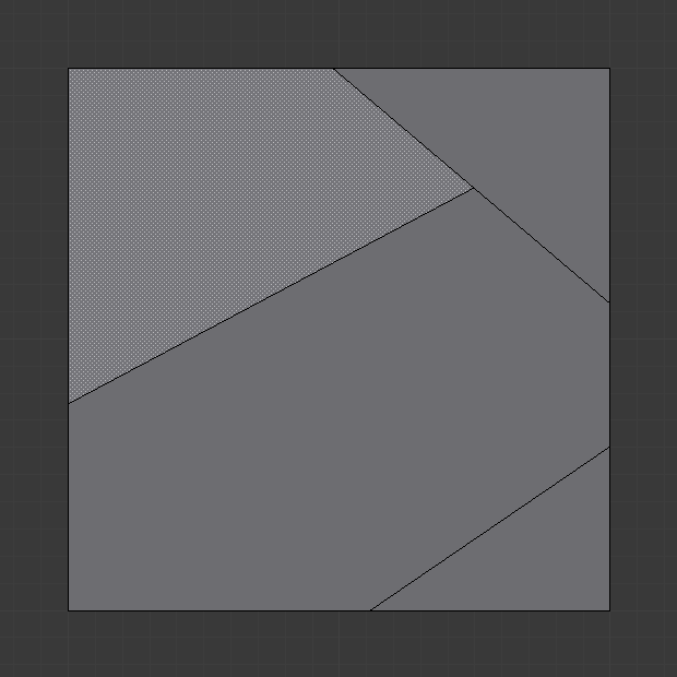
Result of starting new cuts while in the tool.
- Midpoint Snap Shift
Hold to snap the cursor to the midpoint of edges, meaning that all cuts will be performed at the exact center of each cut edge.
- Ignore Snap Ctrl
Hold to make the tool ignore snapping, unlike the default where mouse cursor snaps to near edges.
- Cut Through: C
Allow the Cut tool to cut through to occluded faces, instead of only the visible ones.
- Angle Constrain A
Constrains the cut line to certain degree increments. The increment can be specified in the Tool Settings (see above), or can be typed when angle constraining is active. The default angles are in the plane of the screen, but typing A again makes it relative to the last cut edge. If the last cut edge is ambiguous (because the cut was on a vertex), typing R cycles through the possible reference edges.
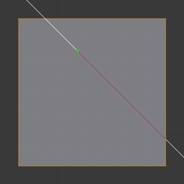
Constraining cut angle.
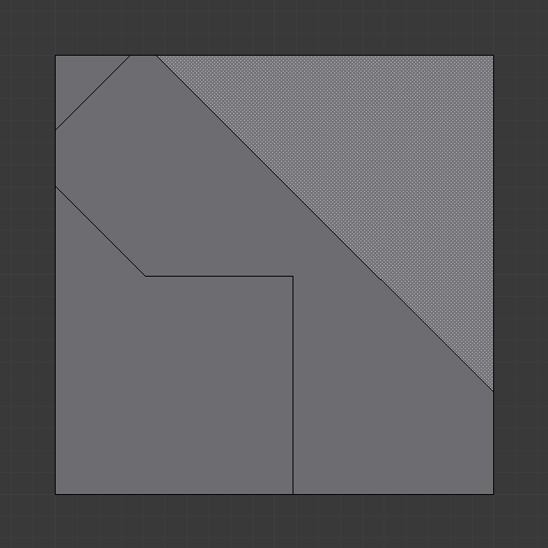
Result of constraining cut angle.
- Axis Constrain X, Y, or Z
Constrains the cut line to one of the coordinate system axes. Initially it will be the global axis with the given name, but pressing the same key again switches to the object’s local axis system. Additionally, if the scene transformation orientation is set to a custom orientation (e.g. from a face), the constraints will be in that coordinate system.
- Visible Measurements S
Shows measurements of the cuts being made: angles with respect to a mesh edge, lengths, or both. Pressing S repeatedly cycles between what can be shown.
Only Distance, Only Angles, Both, None
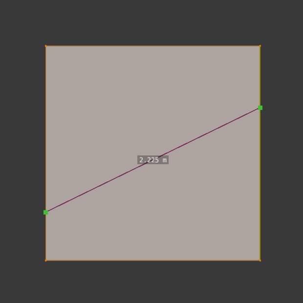
Only Distance.
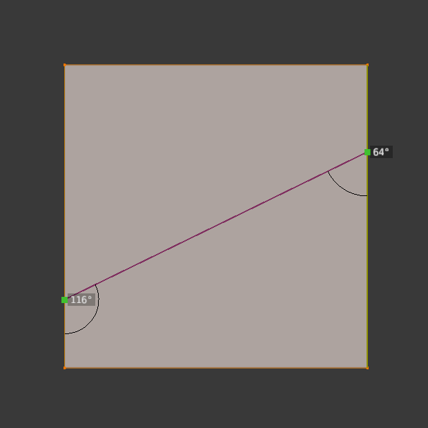
Only Angles.
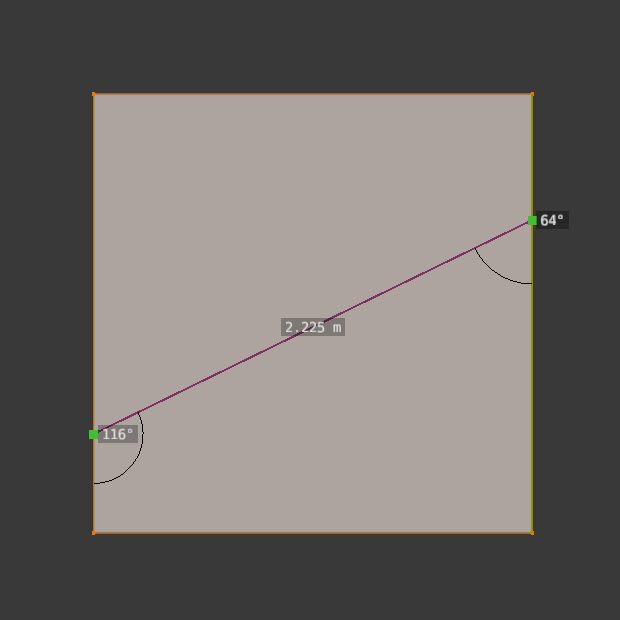
Both Angles and Distance.
- Undo Ctrl-Z
Undoes the previous cut segment. The starting point for the next cut is adjusted accordingly. If a cut is a drag cut, the entire drag cut is undone.
- X-Ray Mode V
Toggles whether or not cuts to segments behind the visible geometry are shown.
Known Limitations
Duplicate Vertices
If you experience problems where duplicate vertices are being created by cuts, this is often caused by too large a near/far clipping range.
Try increasing the Clip Start to avoid this problem, see Depth Troubleshooting for details.
Unconnected Cuts
Cuts that begin or end in the middle of a face, will be ignored.
This is constrained by the kinds of geometry Blender can represent.