Introduction – Вступ

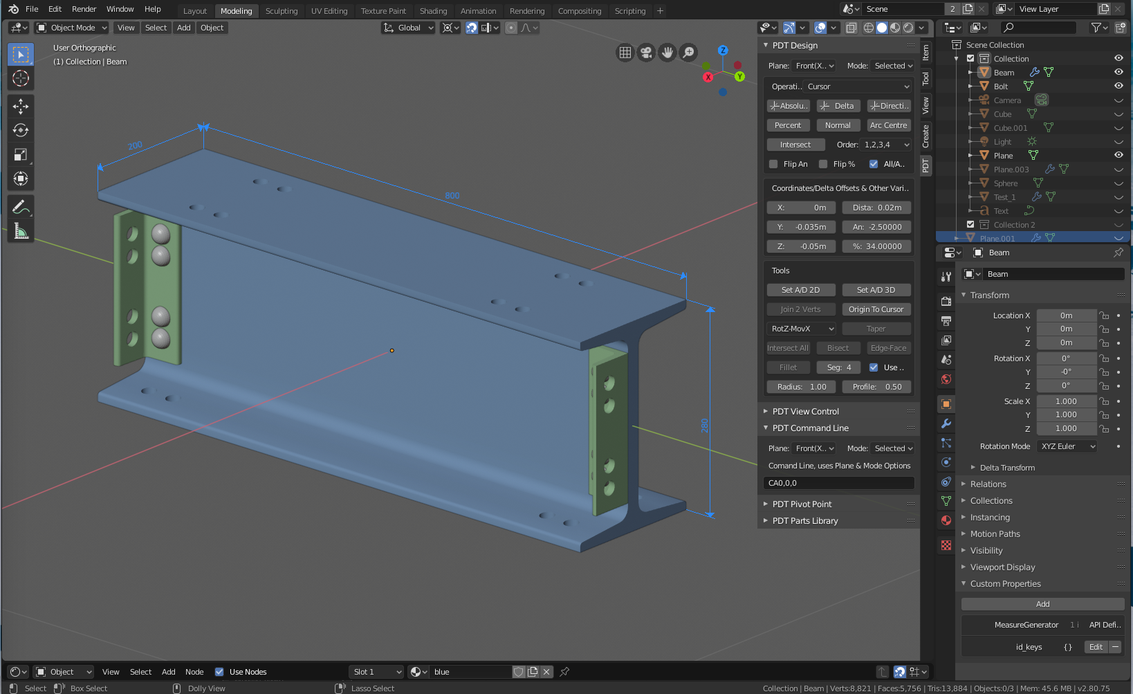
Objects drawn with PDT and Dimensioned with MeasureIt
PDT is designed to work with Blender 2.8, and all subsequent builds. There are no versions for earlier versions of Blender.
The key objective is to make precision modelling easier and more capable in Blender in order to allow Designers of all genres to model accurately.
Interestingly
There is definitely a difference in the way that «CAD Designers» and «Polygon Modellers» work. Polygon Modellers, the traditional Blender users, tend to start off with a basic primitive 3D mesh, like a Cube, or a Cylinder, then start to add Edge Loops to cut it up, to extrude sections to make it more complex, to add «holes» and then work these. They will often use Sub-Division modifiers to make the model more detailed, whereas CAD Designers consider these to largely be unsuitable and reduce accuracy. This means more vertices in the mesh from CAD modeller, but probably about the same after all has been taken into account.
CAD modellers would virtually never trace off a previous drawing, or photograph to model something, they will always work from quoted dimensions only. To this end think about a drawing at a scale of 50:1 - a line of width 0.5mm is effectively 25mm thick in the real world. Many drawings carry the mantra «Do Not Scale» - this is for a reason, old tradition hand-drawn drawings are not necessarily accurately drawn in the first place!
Traditional CAD Designers (I am using the term «CAD» for what is considered to be Computer Aided Design, products like SolidWorks, AutoCAD, MicroStation, etc.) tend to make an accurate flat loop, like the front of a bracket, or wall of a building , then extrude, or «loft» this into a 3D mesh. It has long been considered that this approach leads to more accurate models that could, for example, be used in 3D printing.
PDT aims to introduce this method of working into Blender, for the benefit and inclusion of all genres of CAD Designers and to augment the tools for the Polygon Modeller. It has been developed by a former Mechanical Design Engineer with many years experience in drawing offices, using hand drawing and CAD techniques.
Nomenclature
There is also the situation where CAD Designers and Polygon Modellers use different terms, like Absolute versus World coordinates, Delta versus Incremental, Directional versus Polar. Primitives themselves are also named differently, Vertices, Edges & Faces versus Points, Lines & Polygons - PDT takes care of this by providing a file that users can edit to input their own terms, including their own languages.