Structure
메시를 사용하면 모든 것이 꼭짓점, 모서리, 면 의 세 가지 기본 구조로 구성되요.

메시 구조의 예.
정점
메쉬의 가장 기본적인 부분은 3D 공간에서 단일 지점 또는 위치인 정점 (복수의 꼭짓점) 이에요. 정점은 편집 모드의 3D 뷰포트에서 작은 점으로 표시됩니다. 객체의 정점들은 좌표의 배열로 저장되요.
팁
object origin 을 꼭짓점으로 착각하면 안되요. 비슷해 보이지만 더 크고 선택될 수 없어요.
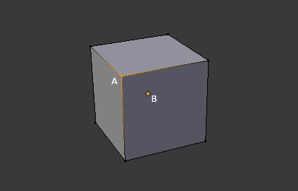
The vertex is labeled as 《A》; the object’s origin dot is labeled as 《B》.
Edges
모서리는 항상 두 꼭지점을 직선으로 연결해요. 모서리는 와이어 프레임 보기에서 메시를 볼 때 표시되는 《wire》 이에요.
Faces
면은 물체의 실제 표면을 만드는 데 사용되요. 메시를 렌더링 할 때 보이는 것이죠. 이 영역에 면이 포함되어 있지 않으면 렌더 된 이미지에 단순히 투명하거나 존재하지 않아요.
면은 모든면에 가장자리가있는 3 개 (삼각형), 4 개 (사각형) 또는 그 이상의 (n 각형) 꼭지점 사이의 영역으로 정의되요. 면은 종종 tris, quads & n-gons 로 축약되요.
삼각형은 항상 평평하므로 계산하기 쉬워요. 반면에 사각형은 《잘 변형》되므로 애니메이션 및 세분화 모델링에 선호된답니다.
법선
기하에서 법선은 일반적으로 삼각형 또는 표면과 같은 무언가에 수직 인 방향 또는 선이지만 선, 곡선의 점에 대한 접선 또는 표면의 점에 대한 접평면에 상대적 일 수도 있어요.
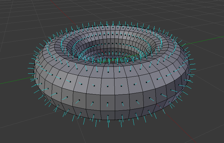
A visualization of the face normals of a torus.
위 그림에서 각 파란색 선은 원환 체의면에 대한 법선을 나타내요. 선은 놓인면에 대해 각각 수직이에요. 시각화는 편집 모드의 : ref :Mesh Display Viewport Overlays panel <mesh-display-normals> 에서 활성화 할 수 있어요.
Properties
Reference
- Panel

Normals panel.
- Auto Smooth
Edges where an angle between the faces is smaller than specified in the Angle field will be smoothed, when shading of these parts of the mesh is set to smooth. This is an easier way to combine smooth and sharp edges.
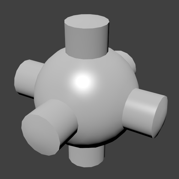
Example mesh with Auto Smooth enabled.
Advanced Smooth Shading & Sharp Edges
기본적으로 블렌더에서는 기본적인 일반 계산 기법을 사용하여 날카로운 모서리는 항상 비 다양체이거나 평면으로 정의된 면 중 하나 이상을 갖는 모서리로 정의되요.
Enabling the Auto Smooth setting adds an extra parameter to define a sharp edge, the Angle threshold between two neighbor faces, above which the edge will always be considered as sharp.
Auto Smooth also enables Custom Split Normals handling, which can be either defined (and edited) as a mesh data layer, or generated on the fly by modifiers. In any case, when a mesh gets custom normals, they always supersede the default ones computed by Auto Smooth.
사용자 정의 법선 수정자는 설정에 따라 법선을 계산하기 위해 날카로운 모서리를 계속 사용할 수 있어요.
Custom Split Normals
Custom Split Normals is a way to tweak/fake shading by pointing normals towards other directions than the default, auto-computed ones. It is mostly used in game development, where it helps counterbalance some issues generated by low-poly objects (the most common examples are low-poly trees, bushes, grass, etc. and the 〈rounded〉 corners).
블렌더는 동일한 꼭지점을 공유하고 부드러운 가장자리로 〈연결된〉 인접면 모서리 세트로 정의 된 〈부드러운 팬〉 베이스에서 사용자 정의 법선을 지원해요. 즉,면 모서리 당, 인접면 모서리 집합 당 또는 정점 당 법선을 가질 수 있어요.
Enabling Custom Split Normals
Reference
- Mode
Edit Mode
- Menu
사용자 정의 분할 법선을 활성화해요. 또한 사용자 정의 법선 편집 도구 (아래 참조)는 편의상 사용자 정의 법선이 아직 활성화되지 않은 경우 활성화되요.
참고
사용자 정의 법선을 사용하는데 필요하므로 이것은 Auto Smooth 을 허용하는 부작용이 있어요. 사용자 정의 법선이 있으면 * 자동 스무딩 * 동작의 각도 임계 값이 비활성화되요. 예리하지 않은 태그가 지정되지 않은 모든 가장자리는 면 사이의 각도를 무시하고 부드러운 것으로 간주되요.
사용자 정의 분할 법선 설정
Reference
- Mode
Edit Mode
- Menu
- Hotkey
Alt-N
사용자 정의 분할 법선을 편집하기 위한 여러 도구가 있어요. 사용자 정의 노멀 메시 편집 도구는 모든 법선 (기본값) 또는 선택한 법선에만 영향을 줄 수 있어요. 특정한 꼭지점 및면과 연관된 사용자 정의 법선을 선택하려면 :
요소 선택 모드를 꼭짓점과 면 모두 만드세요. (두 번째 것을 활성화하려면 Shift-LMB 사용).
하나 이상의 꼭짓점을 선택한 다음 면을 선택해요. 이를 반복하여 더 많은 꼭짓점과 다른 면 등을 선택할 수 있어요. 편집 모드 오버레이 옵션 * 면당 정점 법선을 선으로 표시 *를 켜면 이러한 도구의 효과를 보는 것이 쉬워요.
더 보기
사용자 정의 분할 법선 가져 오기
일부 도구, 특히 CAD 에서 사용되는 도구는 개체를 메시로 테셀레이션 할 떄 불규칙한 형상을 생성하는 셩향이 있습니다 (매우 얇고 긴 삼각형 등). 이러한 도형에서 자동으로 계산 된 법선은 종종 잘못된 아티팩트를 제공하므로 CAD 도구 자체에서 생성 된 법선을 가져와서 사용할 수 있는 것은 중요한 문제이죠.
참고
현재 FBX Importer 및 Alembic Importer 만이 사용자 법선을 가져올 수 있어요.
Topology
Loops
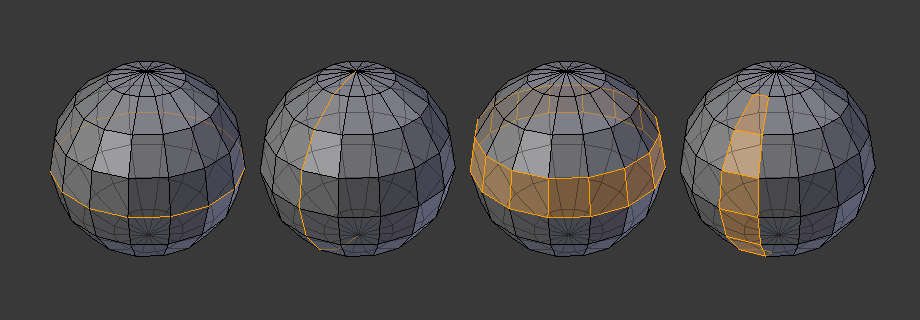
Edge and face loops.
Edge and face loops are sets of faces or edges that form continuous 《loops》 as shown in Fig. Edge and face loops..
In the image above, loops that do not end in poles are cyclic (1 and 3). They start and end at the same vertex and divide the model into two partitions. Loops can be a quick and powerful tool to work with specific, continuous regions of a mesh and are a prerequisite for organic character animation. For a detailed description of how to work with loops in Blender, see: Edge Loop Selection.
참고
Note that loops (2 and 4) do not go around the whole model. Loops stop at so-called poles because there is no unique way to continue a loop from a pole. Poles are vertices that are connected to either three, five, or more edges. Accordingly, vertices connected to exactly one, two or four edges are not poles.
Edge Loops
Loops (1 and 2) in Fig. Edge and face loops. are edge loops. They connect vertices so that each one on the loop has exactly two neighbors that are not on the loop and placed on both sides of the loop (except the start and end vertex in case of poles).
Edge loops are an important concept especially in organic (subsurface) modeling and character animation. When used correctly, they allow you to build models with relatively few vertices that look very natural when used as subdivision surfaces and deform very well in animation.
Take Fig. Edge and face loops. in organic modeling as an example: the edge loops follow the natural contours and deformation lines of the skin and the underlying muscles and are more dense in areas that deform more when the character moves, for example at the shoulders or knees.
Further details on working with edge loops can be found in Edge Loop Selection.
Face Loops
These are a logical extension of edge loops in that they consist of the faces between two edge loops, as shown in loops (3 and 4) in Fig. Edge and face loops.. Note that for non-circular loops (4) the faces containing the poles are not included in a face loop.
Further details on working with face loops can be found in Face Loop Selection.
Poles
See N-poles & E-poles.
Non-Manifold
See Non-manifold.