Bevel (chanfrein)
Référence
- Mode
Mode Édition
- Menu
- Raccourci
Ctrl-B
- Menu
(vertex-only)
- Raccourci
Maj-Ctrl-B (sommet seulement)
The Bevel tool allows you to create chamfered or rounded corners on geometry. A bevel is an effect that smooths out edges and corners.
Real world edges are very seldom exactly sharp. Not even a knife blade edge can be considered perfectly sharp. Most edges are intentionally beveled for mechanical and practical reasons.
Les biseaux sont aussi utiles pour donner du réalisme à des modèles non organiques. Dans le monde réel, les arêtes sur des objets captent la lumière et modifient l’ombrage autour des arêtes. Ceci donne un aspect réalistique solide contrairement aux objets non chanfreinés qui ont un aspect trop parfait.
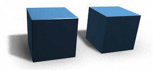
cubes avec et sans chanfrein.
Utilisation
The Bevel Edges tool works only on selected edges with exactly two adjacent faces. It will recognize any edges included in a vertex or face selection as well, and perform the bevel the same as if those edges were explicitly selected. In « vertex only » mode, the Bevel Vertices tool works on selected vertices instead of edges, and there is no requirement about having any adjacent faces. The Bevel tool smooths the edges and/or « corners » (vertices) by replacing them with faces making smooth profiles with a specified number of segments (see the options below for details about the bevel algorithm).
Use Ctrl-B or a method listed above to run the tool. Move the mouse to interactively or type a number to specify the bevel offset, and scroll the Wheel to increase or decrease the number of segments (see below).
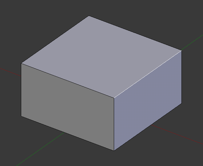
Arête sélectionnée avant biseautage.¶ |
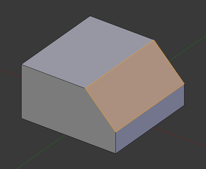
Résultat de biseautage (un segment).¶ |
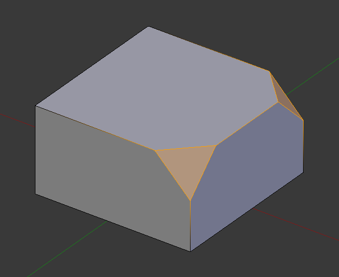
Résultat de biseautage (sommet uniquement).¶ |
Note
Le biseautage normal (arête) fonctionne seulement sur des arêtes qui ont exactement deux faces attachées. Le biseautage de sommet n’a pas de telles restrictions.
Options
- Amount A
Vous pouvez modifier le niveau de biseautage en déplaçant la souris vers l’objet et loin de l’objet, un peu comme avec les outils de transformation. La signification exacte de la valeur dépend de l’option Amount Type (voir ci-dessous). Comme d’habitude, la mise à l’échelle peut être contrôlée plus finement en maintenant Maj pour mettre à l’échelle par pas de 0.001. LMB finalise l’opération, RMB ou Échap. annule l’action.
- Amount Type M
Sélectionne la manière dont la valeur Amount contrôle la taille du biseau. Selon la sélection, Amount est :
- Offset
La distance d’une nouvelle arête à partir de l’originale.
- Width
La largeur de la face du biseau.
- Depth
La distance perpendiculaire à partir de l’arête d’origine à la face du biseau.
- Percent
The percentage of the length of adjacent edges that the new edges slide.
For vertex-only bevels, the Offset and Depth types measure from the original vertex, and the Width type is measured from a new vertex to the center of the new face (as half the amount).
- Segments S
Le nombre de segments dans le chanfrein peut être défini en utilisant la Molette`de la souris pour augmenter ou diminuer cette valeur. Plus le nombre de segments est grand, plus le chanfrein est lisse. Ou pressez :kbd:`S pour modifier le nombre avec des mouvements de souris, ainsi que la saisie numérique.
Alternatively, you can manually enter a segment number value while using the tool, or in the Mesh Tool options panel after using the tool.
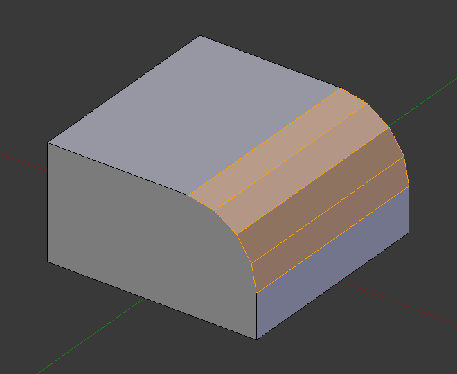
Chanfrein avec quatre segments.
- Profile P
This is a number between 0 and 1 that controls the shape of the profile (side view of a beveled edge). The default value, 0.5, gives a circular arc (if the faces meet at right angles). Values less than that give a flatter profile, with 0.25 being exactly flat, and values less than that giving a concave bevel. Values more than 0.5 give a more convex profile. Similarly as Segments it can be set with mouse movements and numeric input after toggling P.
- Vertex Only V
Quand l’option est sélectionnée, l’outil est en mode « vertex only », et seuls les sommets seront chanfreinés.
- Clamp Overlap C
Limits the width of each beveled edge so that edges cannot cause overlapping intersections with other geometry.
- Loop Slide
If there are unbeveled edges along with beveled edges into a vertex, the bevel tries to slide along those edges when possible. Turning the option off can lead to more even bevel widths.
- Mark Seams U
If a seam edge crosses a non-seam one and you bevel all of them, this option will maintain the expected propagation of seams.
- Mark Sharp K
Similar to Mark Seams, but for sharp edges.
- Material
The Material number specifies which material should be assigned to the new faces created by the Bevel tool. With the default, -1, the material is inherited from the closest existing face (« closest » can be a bit ambiguous). Otherwise, the number is the slot index of the material to use for all newly created faces.
- Harden Normals H
When enabled, the per-vertex face normals of the bevel faces are adjusted to match the surrounding faces, and the normals of the surrounding faces are not affected. This will keep the surrounding faces flat (if they were before), with the bevel faces shading smoothly into them. For this effect to work, custom split normals need to be enabled, which requires Auto Smooth to be enabled (see Normals). As a convenience, that option will be enabled for you if it is not already when you enable Harden Normals here.
- Face Strength Mode
Set Face Strength on the faces involved in the bevel, according to the specified mode. This can be used in conjunction with a Weight Normals Modifier (with the Face Influence option checked).
- None
Do not set face strength.
- New
Set the face strength of new faces along edges to Medium, and the face strength of new faces at vertices to Weak.
- Affected
In addition to those set for the New case, also set the faces adjacent to new faces to have strength Strong.
- All
In addition to those set for the Affected option, also set all the rest of the faces of the model to have strength Strong.
- Outer Miter O
A miter is formed when two beveled edges meet at an angle. On the side where the angle is greater than 180 degrees, if any, it is called an outer miter. This option specifies the pattern that Blender uses at an outer miter.
- Sharp
Edges meet at a sharp point, with no extra vertices introduced on the edges.
- Patch
Edges meet at a sharp point but in addition, two extra vertices are introduced near the point so that the edges and faces at the vertex may be less pinched together than what occurs in the Sharp case. The Spread slider controls how far the new vertices are from the meeting point.
- Arc
Two vertices are introduced near the meeting point, and a curved arc joins them together. The Spread slider controls how far the new vertices are from the meeting point. The Profile slider controls the shape of the arc.
The current choices are shown in this diagram, where the outer miter is along the horizontal surface.
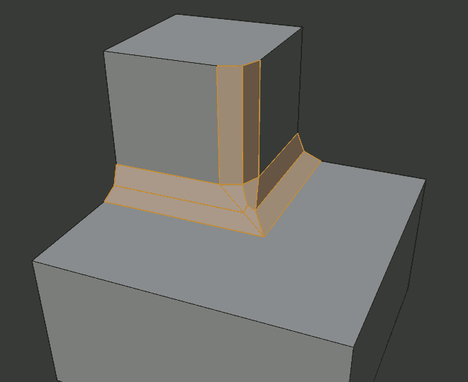
Sharp outer miter.
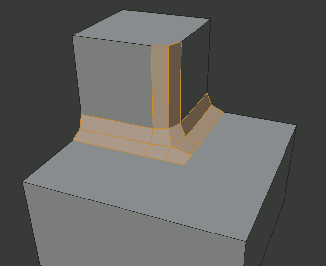
Patch outer miter.
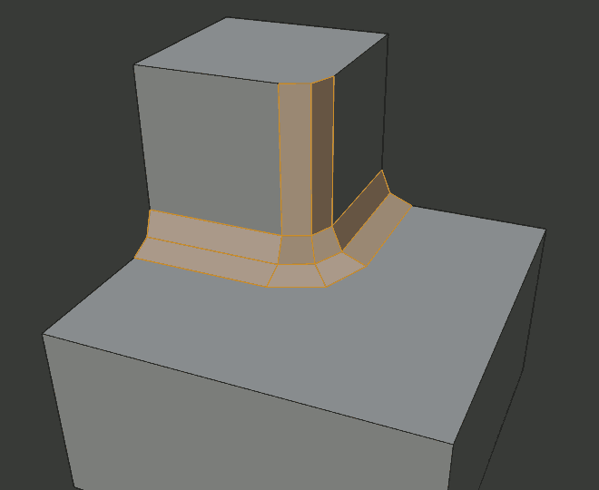
Arc outer miter.
- Inner Miter I
An Inner Miter is formed when the angle between two beveled edges is less than 180 degrees. This option specifies the pattern Blender uses at an inner miter. The options are the same as for Outer Miter, except that Patch makes no sense and is therefore omitted. Inner miters are shown in the following diagram, where two inner miters are on the vertical surfaces.
Sharp inner miter.

Arc inner miter.
- Spread
The value used to spread extra vertices apart for Outer and Inner Miters.
- Intersection Method N
When more than two beveled edges meet at a vertex, a mesh is created as a way to complete the intersection between the generated geometry. This option controls the method used to create that mesh.
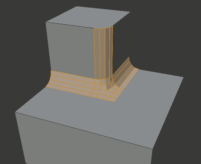
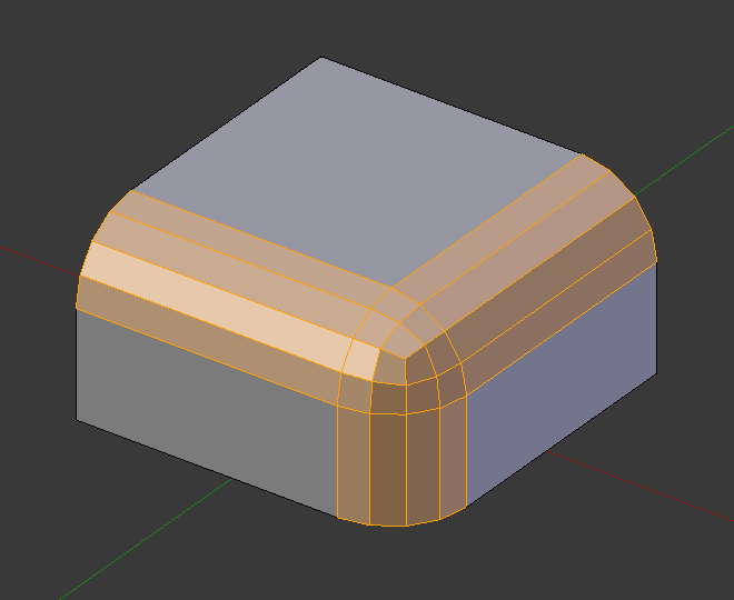
- Grid Fill
The default method for building intersections, useful when a smooth continuation of the bevel profile is desired. Without Custom Profile enabled, the curve of the profile continues through the intersection, but with a custom profile it just creates a smooth grid within the intersection’s boundary.
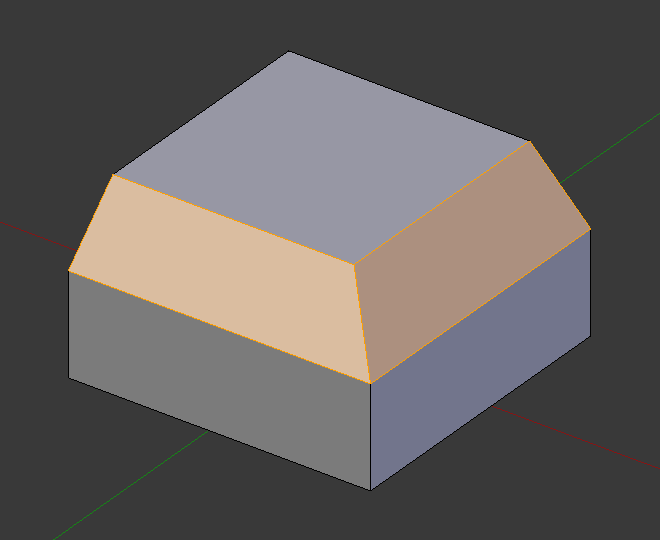
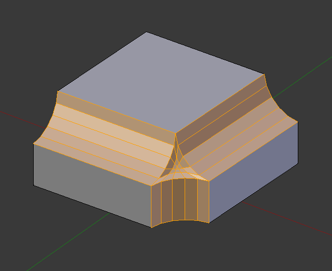
- Cutoff
Creates a cutoff face at the end of each beveled edge coming into the vertex. This is most useful for custom profiles when the new intersection is too complex for a smooth grid fill.
With a three way intersection, when the inner corners of the cutoff profiles faces meet at the same location, no center face is created.
The direction of the cutoff faces depends on the original vertex’s normal.
Intersection method options.¶ 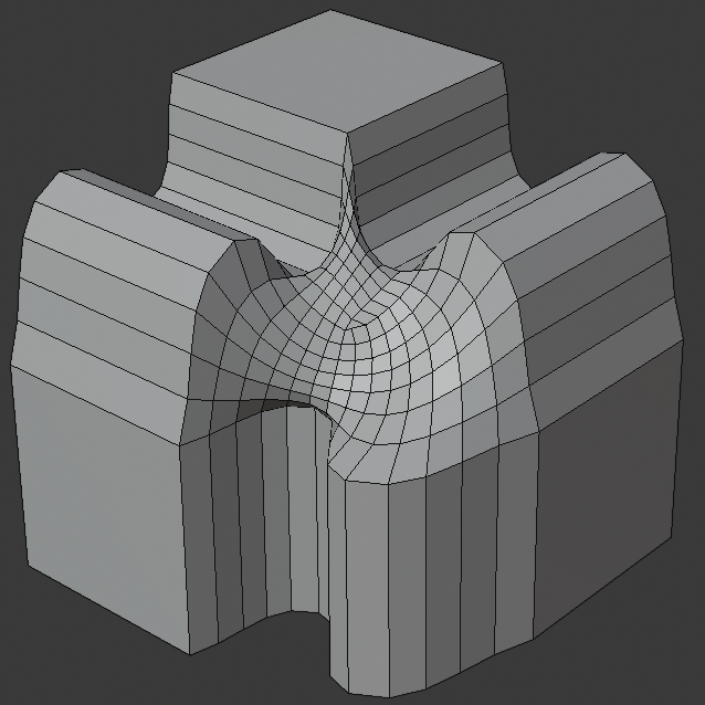
Grid fill intersection method.
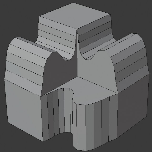
Three way cutoff intersection where the inner vertices are merged.
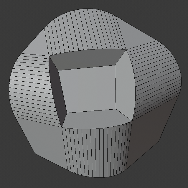
Cutoff intersection method with a center face.
- Custom Profile Z
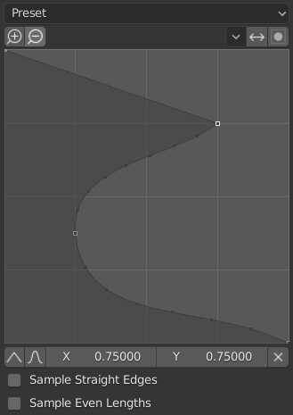
The custom profile widget.
This widget allows the creation of a user-defined profile with more complexity than with the single profile parameter. The modal tool allows toggling the custom profile, but the shape of the profile is only editable in the options panel after the operation is confirmed.
The profile starts at the bottom right of the widget and ends at the top left, as if it were between two edges meeting at a right angle. Control points are created in the widget and then the path is sampled with the number of segments from the bevel modifier.
- Presets
The Support Loops and Steps presets are built dynamically depending on the number of segments in the bevel. If the number of segments is changed, the preset will have to be re-applied.
- Reverse
The Reverse button flips the orientation of the profile for all beveled edges.
- Clipping
The Clipping toggle allows control points to be moved beyond the initial boundary, allowing the bevel to add volume to the mesh rather than just removing it.
Note
The Profile slider is still useful when miters are enabled because it still controls the shape of the miter profiles.
Sampling
Samples will first be added to each control point, then if there are enough samples, they will be divided evenly between the edges. The Sample Straight Edges option toggles whether the samples are added to edges with sharp control points on either side. If there aren’t enough samples to give each edge the same number of samples, they will just be added to the most curved edges, so it is recommended to use at least as many segments as there are control points.
Exemples
Résultat de biseautage d’arêtes multiples.¶ |
Un autre exemple de biseautage d’arêtes multiples.¶ |
Un exemple utilisant Profile=0.150.¶ |
Voir aussi
Modificateur Bevel
The Bevel Modifier is a non-destructive alternative to the Bevel tool.