Le modificateur Bevel
The Bevel modifier bevels the edges of the mesh it is applied to, with some control of how and where the bevel is applied to the mesh.
It is a non-destructive alternative to the Bevel Operation in Edit Mode.
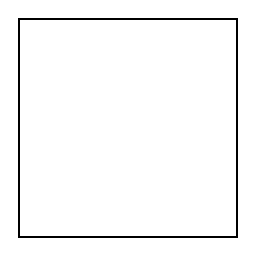
Non biseauté.¶ |
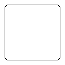
Biseauté.¶ |
Options
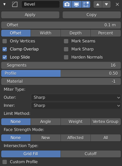
The Bevel modifier.
- Width
The size of the bevel effect. See Width Method below.
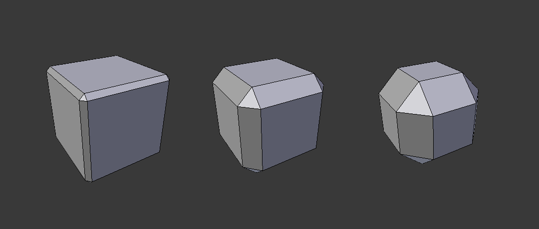
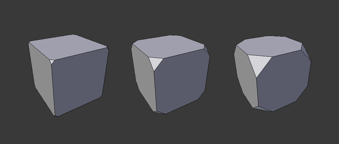
Three Cubes with 0.1, 0.3 and 0.5 bevel widths.
- Segments
Le nombre de edge loops ajoutées sur la face du biseau.
- Profile
La forme du biseau, de concave à convexe. N’a pas d’effet si Segments est plus petit que 2.
- Material
L’indice de l’emplacement du matériau à utiliser pour le biseau. Quand il est fixé à -1, le matériau de la face d’origine la plus proche sera utilisé.
- Only Vertices
When enabled, only the areas near vertices are beveled, the edges remain unchanged.
Three cubes with 0.1, 0.3 and 0.5 bevel widths, with Only Vertices option enabled.
- Clamp Overlap
Limits the width of each beveled edge so that edges cannot cause overlapping intersections with other geometry.
- Loop Slide
If there are unbeveled edges along with beveled edges into a vertex, the bevel tries to slide along those edges when possible. Turning the option off can lead to more even bevel widths.
- Mark Seams
If a seam edge crosses a non-seam one and you bevel all of them, this option will maintain the expected propagation of seams.
- Mark Sharp
Similar to Mark Seams, but for sharp edges.
- Harden Normals
When enabled, the per-vertex face normals of the bevel faces are adjusted to match the surrounding faces, and the normals of the surrounding faces are not affected. This will keep the surrounding faces flat (if they were before), with the bevel faces shading smoothly into them. For this effect to work, you need custom normals data, which requires Auto Smooth option to be enabled (see Normals).
- Limit Method
Utilisé pour contrôler où les biseaux seront appliqués au maillage.
- None
Aucune limite, toutes les arêtes seront biseautées.
- Angle
Seules les arêtes où les faces adjacentes forment un angle plus petit que le seuil défini seront biseautées. Destiné à vous permettre de biseauter seulement les arêtes tranchantes d’un objet sans affecter ses surfaces lisses.
- Weight
Utilisez chaque poids de biseautage des arêtes pour déterminer la largeur du biseau. Quand le poids du biseau est 0.0, aucun biseau n’est appliqué. Voir ici à propos de l’ajustement des poids de biseau.
- Vertex Group
Utilisez les poids d’un groupe de sommets pour déterminer la largeur du biseau. Quand le poids du sommet est 0.0, aucun biseau n’est appliqué. Une arête n’est biseautée que si ses deux sommets sont dans le groupe de sommets. Voir ici à propos de l’ajustement des poids de groupes de sommets.
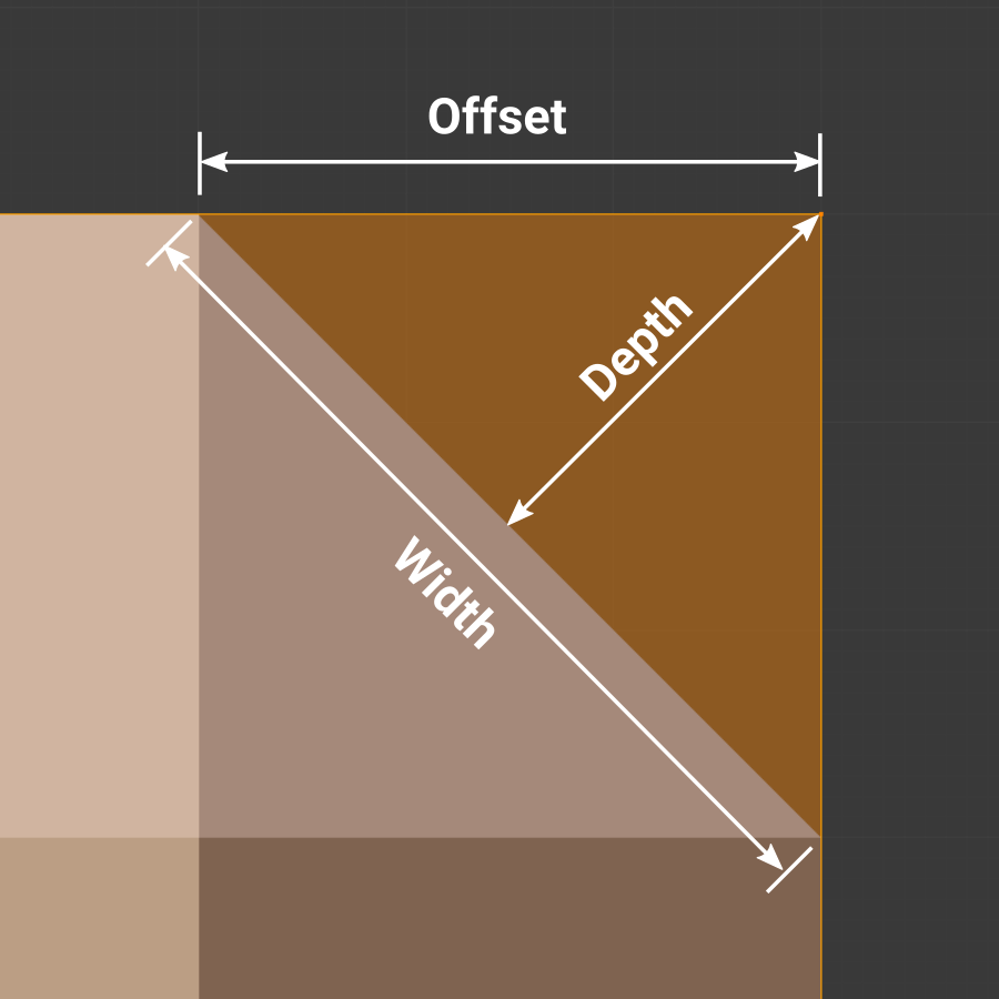
- Width Method
Déclare la manière dont Width sera interprété pour déterminer le niveau de biseautage.
Width methods.
- Offset
Valeur interprétée comme la distance du bord d’origine au bord de la face biseautée.
- Width
Valeur interprétée comme la distance entre les deux nouveaux bords formés par le biseau.
- Depth
Est la distance perpendiculaire de la nouvelle face de biseau au bord d’origine.
- Percent
Comparable à Offset mais la valeur est interprétée comme un pourcentage de longueur du bord adjacent.
- Set Face Strength Mode
Set Face Strength on the faces involved in the bevel, according to the mode specified here. This can be used in conjunction with a following Weighted Normals modifier (with the Face Influence option checked).
- None
Do not set face strength.
- New
Set the face strength of new faces along edges to Medium, and the face strength of new faces at vertices to Weak.
- Affected
In addition to those set for the New case, also set the faces adjacent to new faces to have strength Strong.
- All
In addition to those set for the Affected case, also set all the rest of the faces of the model to have strength Strong.
- Miter Patterns
A miter is formed when two beveled edges meet at an angle. On the side where the angle is greater than 180 degrees, if any, it is called an outer miter. If it is less than 180 degrees, then it is called an inner miter. The outer and inner miters can each be set to one of these patterns:
- Sharp
Edges meet at a sharp point, with no extra vertices introduced on the edges.
- Patch
Edges meet at a sharp point but in addition, two extra vertices are introduced near the point so that the edges and faces at the vertex may be less pinched together than what occurs in the Sharp case. This pattern does makes no sense for inner miters, so it behaves like Arc for them.
The Spread slider controls how far the new vertices are from the meeting point.
- Arc
Two vertices are introduced near the meeting point, and a curved arc joins them together.
The Spread slider controls how far the new vertices are from the meeting point.
The Profile slider controls the shape of the arc.
Diagrams of the miter patterns.¶ 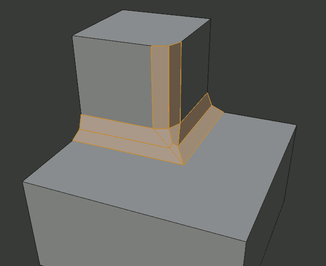
Sharp outer miter.
Patch outer miter.
Arc outer miter.
Sharp inner miter.

Arc inner miter.
- Spread
The value used to spread extra vertices apart for non-sharp miters.
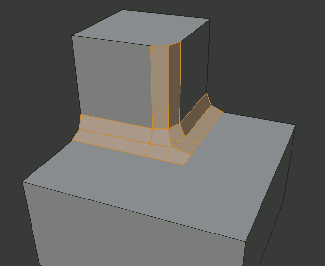
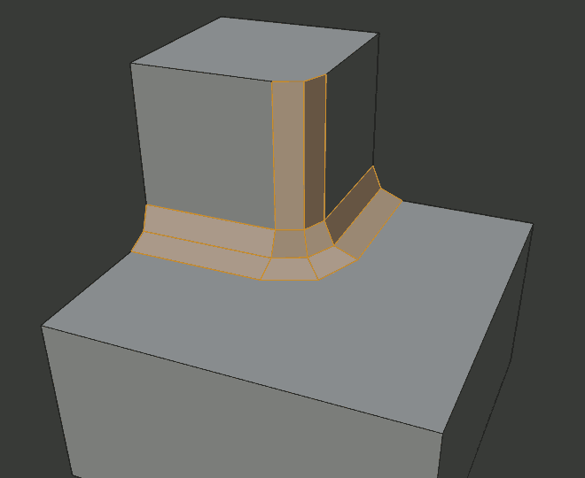
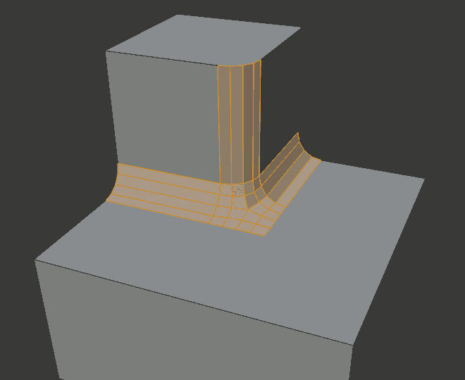
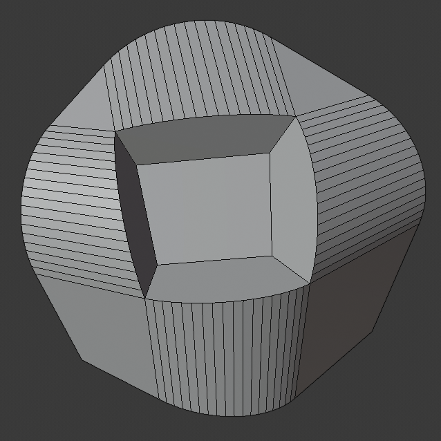
- Intersection Method
When more than two beveled edges meet at a vertex, a mesh is created as a way to complete the intersection between the generated geometry. This option controls the method used to create that mesh.
- Grid Fill
The default method for building intersections, useful when a smooth continuation of the bevel profile is desired. Without Custom Profile enabled, the curve of the profile continues through the intersection, but with a custom profile it just creates a smooth grid within the boundary of the intersection.
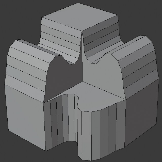
- Cutoff
Creates a cutoff face at the end of each beveled edge coming into the vertex. This is most useful for custom profiles when the new intersection is too complex for a smooth grid fill.
With a three way intersection, when the inner corners of the cutoff profiles faces meet at the same location, no center face is created.
The direction of the cutoff faces depends on the original vertex’s normal.
Intersection method options.¶ 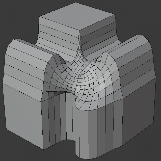
Grid fill intersection method.
Three way cutoff intersection where the inner vertices are merged.
Cutoff intersection method with a center face.
- Custom Profile
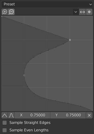
The custom profile widget.
This widget allows the creation of a user-defined profile with more complexity than with the single profile parameter. The modal tool allows toggling the custom profile, but the shape of the profile is only editable in the options panel after the operation is confirmed.
The profile starts at the bottom right of the widget and ends at the top left, as if it were between two edges meeting at a right angle. Control points are created in the widget and then the path is sampled with the number of segments from the bevel modifier.
- Presets
The Support Loops and Steps presets are built dynamically depending on the number of segments in the bevel. If the number of segments is changed, the preset will have to be re-applied.
- Reverse
The Reverse button flips the orientation of the profile for all beveled edges.
- Clipping
The Clipping toggle allows control points to be moved beyond the initial boundary, allowing the bevel to add volume to the mesh rather than just removing it.
Note
The Profile slider is still useful when miters are enabled because it still controls the shape of the miter profiles.
Sampling
Samples will first be added to each control point, then if there are enough samples, they will be divided evenly between the edges. The Sample Straight Edges option toggles whether the samples are added to edges with sharp control points on either side. If there aren’t enough samples to give each edge the same number of samples, they will just be added to the most curved edges, so it is recommended to use at least as many segments as there are control points.