Керувальні Точки – Control Points
Видавити Криву та Перемістити – Extrude Curve and Move
Орієнтир – Reference
- Режим – Mode
Режим Редагування – Edit Mode
- Меню – Menu
«Поверхня > Видавити Криву та Перемістити» –
- Shortcut – Скорочення
E
Unlike meshes or curves, you cannot generally directly add new control points to a surface, as you can only extend a surface by adding a whole U or V row at once. The only exception is when working on a NURBS surface curve, i.e. a surface with only one control point on each U or V row. In this special case, all works exactly as with curves.
Most of the time, only extrusion is available. As usual, once the tool is activated the extrusion happens immediately and you are placed into select mode, ready to drag the new extruded surface to its destination.
Для розуміння дуже важливими є дві речі:
Surfaces are 2D objects. So you cannot extrude anything inside a surface (e.g. «inner» row); it would not make any sense!
Керувальна «ґратка» повинна залишатися «квадратовою», а це означає, що ви можете видавлювати тільки ряд цілком, а не частини рядів тут і там…
Підсумовуючи, засіб Extrude буде працювати тільки, коли попередньо один і тільки один межовий ряд цілком виділено, інакше нічого не трапиться.
Примітка
As for curves, you cannot create a new surface in your object out of nowhere. However, unlike for curves, there is no «cut» option allowing you to separate a surface into several parts, so you only can create a new surface by Duplicating an existing one, or adding a new one with the Add menu.
Приклади – Examples
Ілюстрації з Вибирання керувальної точки. до Видавлення. показують типове видавлення уздовж сторони поверхні.
На Ілюстраціях Вибирання керувальної точки. та Вибір Ряду Керувальних Точок. межовий ряд керувальних точок було підсвічено вибиранням одиничної керувальної точки, а потім використано Вибрати Ряд Керувальних Точок – Select Control Point Row для вибору решти керувальних точок.
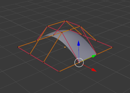
Вибирання керувальної точки. |
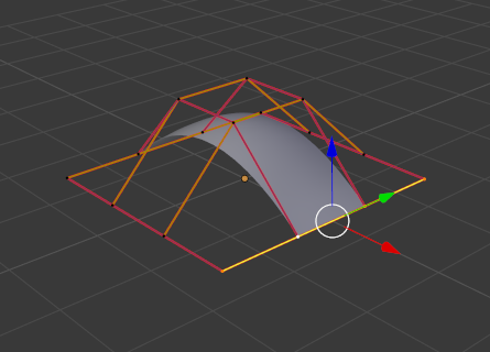
Вибір Ряду Керувальних Точок. |
The edge is then extruded as shown in Fig. Видавлення.. Notice how the mesh has bunched up next to the highlighted edge. That is because the new extruded surface section is bunched up there as well.
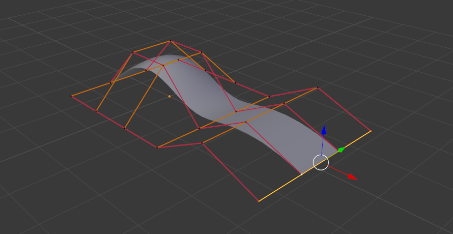
Видавлення.
При переміщуванні цього нового підрозділу від даної області поверхня починає «розправлятися».
Ви можете продовжувати цей процес видавлення або додавати нові підрозділи поверхні, допоки ви не досягнете фінально потрібної вам форми моделі.
Зробити Сегмент – Make Segment
Орієнтир – Reference
- Режим – Mode
Режим Редагування – Edit Mode
- Меню – Menu
«Поверхня > Зробити Сегмент» –
- Shortcut – Скорочення
F
Just like curves, merging two surfaces requires that a single edge, a border row of control points, from two separate surfaces is selected. This means that the surfaces must be part of the same object. For example, you cannot join two surfaces while in Object Mode – but you can of course, as with any objects of the same type, join two or more Surface objects – they just will not be «linked» or merged in a single one.
This tool is equivalent to creating edges or faces for meshes (hence its shortcut).
The selection must contain only border rows of the same resolution
(with the same number of control points),
else Blender will try to do its best to guess what to merge with what,
or the merge will fail (either silently, or stating that Resolution does not match
if rows with different number of points are selected, or that there is Too few selections to merge
if you only selected points in one surface…). To select control points of different surfaces,
in the same object, you must use either box select or circle select; Ctrl-LMB will not work.
So to avoid problems, you should always only select border rows with the same number of points… Note that you can join a border U row of one surface with a border V row of another one, Blender will automatically «invert» the axis of one surface for them to match correctly.
Криві поверхні НОРБС часто використовуються для створення таких об’єктів, як корпуси, оскільки вони визначають поперечні перерізи по всьому об’єкту, і вони просто мають «покривати» їх, як описано вище, щоб отримати гарну, плавну та гармонічну форму.
Приклади – Examples
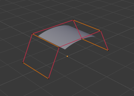
Fig. Готовність до сполучення. is an example of two NURBS surface curves, not NURBS curves, in Edit Mode, ready to be joined. Fig. Завершене сполучення. is the result of joining the two curves.
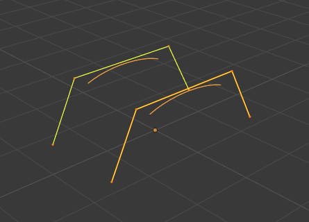
Готовність до сполучення. |
Завершене сполучення. |
Smooth – Згладження
Орієнтир – Reference
- Режим – Mode
Режим Редагування – Edit Mode
- Меню – Menu
«Поверхня > Керувальні Точки > Згладження» –
Повторювано згладжує вибрані керувальні точки шляхом скорочування відстані між сусідніми керувальними точками.
Гачки – Hooks
Орієнтир – Reference
- Режим – Mode
Режим Редагування – Edit Mode
- Меню – Menu
«Поверхня > Керувальні Точки > Гачки» –
- Shortcut – Скорочення
Ctrl-H
Hooks – гачки можуть додаватися для керування однією або кількома точками за допомогою інших об’єктів.
Зробити Приріднення до Вершин – Make Vertex Parent
Орієнтир – Reference
- Режим – Mode
Режим Редагування – Edit Mode
- Меню – Menu
«Поверхня > Керувальні Точки > Зробити Приріднення до Вершин» –
- Shortcut – Скорочення
Ctrl-P
Ви можете робити інші вибрані об’єкти нащадками – children однієї або трьох керувальних точок, як і із сітьовими об’єктами.
To select a mesh (that is in view) while editing a surface, Ctrl-P click on it. Select either one or three control points, then Ctrl-LMB the object and use Ctrl-P to make a vertex parent. Selecting three control points will make the child follow the median point between the three vertices. An alternative would be to use a Child Of constraint. See also the Curve modifier.