Structure
Many of the concepts from curves, especially NURBS ones, carry directly over to NURBS surfaces, such as control points, Order, Weight, Resolution, etc. Here we will just talk about the differences.
It is very important to understand the difference between NURBS curves and NURBS surfaces: the first one has one dimension, the latter has two. Blender internally treats NURBS surfaces and NURBS curves completely differently. There are several attributes that separate them but the most important is that a NURBS curve has a single interpolation axis (U) and a NURBS surface has two interpolation axes (U and V).
However, you can have „2D“ surfaces made of curves (using the extrusion tools, or, to a lesser extent, the filling of closed 2D curves). And you can have „1D“ curves made of surfaces, like a NURBS surface with only one row (either in U or V direction) of control points produces only a curve…
Visually you can tell which is which by entering Edit Mode and looking at the 3D Viewport header: either the header shows Surface or Curve as one of the menu choices. Also, you can extrude a whole NURBS surface curve to create a surface, but you cannot with a simple NURBS curve.
Control Points, Rows and Grid
Control points for NURBS surfaces are the same as for NURBS curves. However, their layout is quite constraining. The concept of „segment“ disappears, replaced by „rows“ and the overall „grid“.
A „row“ is a set of control points forming one „line“ in one interpolation direction (a bit similar to edge loops for meshes). So you have „U rows“ and „V rows“ in a NURBS surface. The key point is that all rows of a given type (U or V) have the same number of control points. Each control point belongs to exactly one U row and one V row.
All this forms a „grid“, or „cage“, the shape of which controls the shape of the NURBS surface. A bit like a lattice…
This is very important to grasp: you cannot add a single control point to a NURBS surface; you have to add a whole U or V row at once (in practice, you will usually use the Extrude tool, or perhaps the Duplicate one, to add those…), containing exactly the same number of points as the others. This also means that you will only be able to „merge“ different pieces of surfaces if at least one of their rows matches together.
Weight
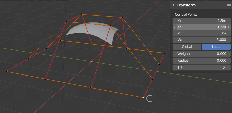
Similar to NURBS Splines NURBS Surface control points have a weight property. This weight property controls how much influence the control point has on the surface. This weight should not be confused with the Goal Weight, which is used only for soft body simulations. The NURBS control point weight can be adjusted in the W number field of the Transform panel.
In Fig. One control point with a weight of 5. a single control point, labeled „C“, has had its Weight set to 5.0 while all others are at their default of 1.0. As you can see, that control point pulls the surface towards it.

One control point with a weight of 5.
Opomba
If all the control points have the same Weight then each effectively cancels each other out. It is the difference in the weights that cause the surface to move towards or away from a control point.
Preset Weights
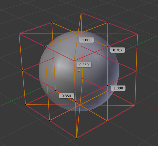
NURBS can create pure shapes such as circles, cylinders, and spheres (note that a Bézier circle is not a pure circle). To create pure circles, spheres, or cylinders, you must set to specific values the weights of the control points. This is not intuitive, and you should read more on NURBS before trying this.
To create a sphere with 2D surfaces, its the same principle as with a 2D circle. You will note that the four different weights needed for creating a sphere (1.0, 0.707 = sqrt(0.5), 0.354 = sqrt(2)/4, and 0.25).

A sphere surface.