GPU Compositor
The new GPU accelerated compositor introduced in Blender 3.5 and is currently used for viewport compositing.
Data
Dimensionality
Compositing nodes operate on data that is either an image or a dimensionless single value. For instance, the Levels node outputs a single value, while the Render Layers node outputs an image. Node inputs that expect a single value assume a default value if an image is given and ignore the image completely, for instance, the Transform node expects single values for its inputs and will assume default values if images were given to those inputs. The default values are those that are considered identity and thus have no effect on the output, so for the Transform node, the X, Y, and Angle inputs will have a default value of zero, while the Scale input will have a default value of one. On the other hand, if node inputs that expect an image are given a single value, the single value will be assumed to cover the whole compositing space. For instance, the Filter node expect its Factor input to be an image, but if a single value is given, it will be assumed to be the same for all pixels.
Type
Three types of data exist, all of which are stored in half precision formats:
- Float
A signed floating-point number. Integer data is also stored as floats because no integer type exist.
- Vector
A 4D vector. While it is 4D, it can have different interpretations depending on the node that uses it. It can be treated as a 2D vector with the last two components ignored, for instance, the Vector input of the Displace node is treated as a 2D vector. It can be treated as a 3D vector with the last component ignored, for instance, the Vector input of the Seperate XYZ node is treated as a 3D vector. It can be treated as two consecutive 2D vectors. For instance the Velocity Pass as expected by the Vector Blur node is assumed to have the 2D Previous Velocity in the X and Y components of the vector and the 2D Next Velocity in the Z and W components of the vector.
- Color
A 4D vector storing the Red, Green, Blue, and Alpha of the color. The color is free form and does not conform to a specific color space or alpha storage model, instead, appropriate nodes will have settings to control the representation of their output and nodes exist to convert between the different representations.
Implicit Conversion
In case a node input is given data of type other than its own type, the following implicit conversions are performed:
Source |
Target |
Conversion |
|---|---|---|
Float |
Vector |
f => Vector(f, f, f, 0) |
Float |
Color |
f => Color(f, f, f, 1) |
Vector |
Float |
(x, y, z, w) => Average(x, y, z) |
Vector |
Color |
(x, y, z, w) => Color(x, y, z, 1) |
Color |
Float |
(r, g, b, a) => Average(r, g, b) |
Color |
Vector |
(r, g, b, a) => Vector(r, g, b, 0) |
The following example demonstrates implicit conversion between a color type and a float type, since the Math node expect float inputs.
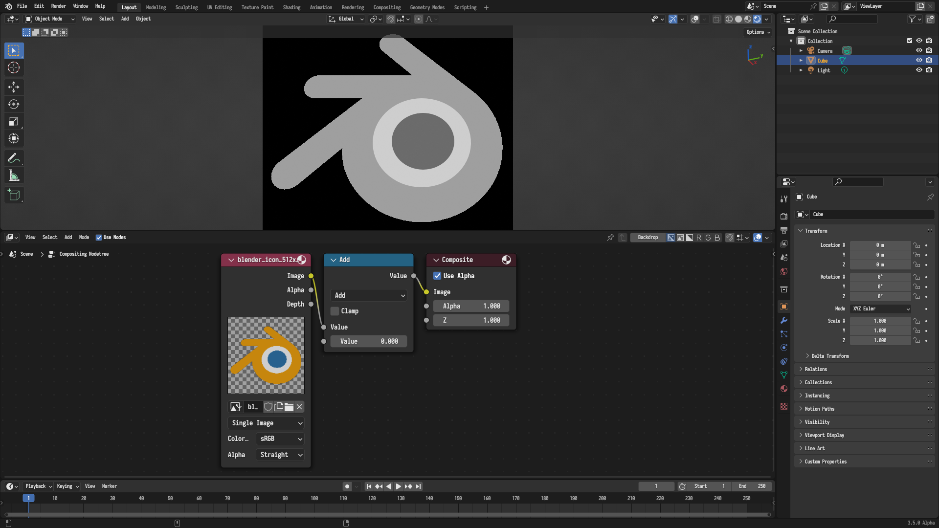
An example that demonstrates implicit conversion between a color type and a float type, since the Math node expects float inputs.
Compositing Space
Image Domain
The compositor is designed in such a way as to allow compositing in an infinite compositing space. Consequently, images are not only represented by their size, but also by their transformation in that space, much like 3D objects have transformations. An identity transformation represents an image that is centered in space. The rectangular area occupied by an image in that space as defined by its transformation and size is called the Domain of the image. The figure below demonstrates the domains of two example images.
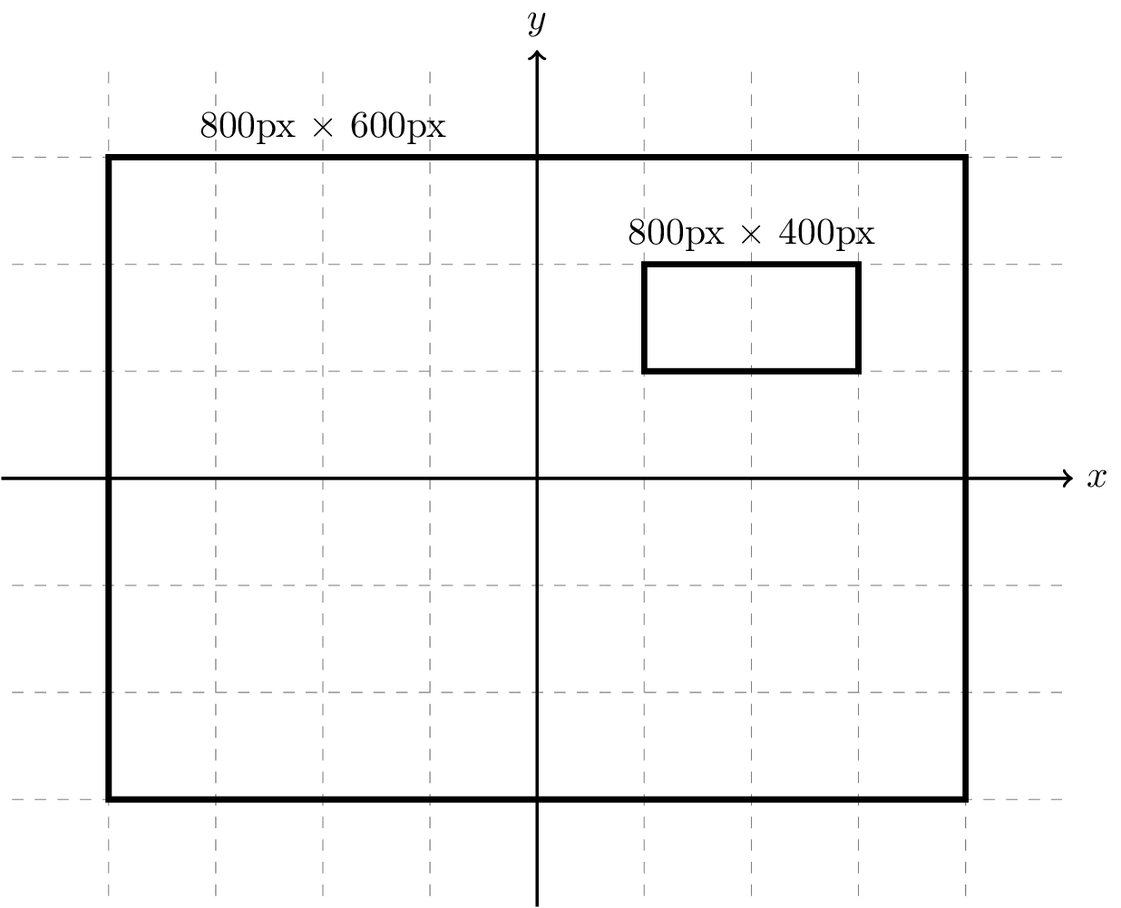
The domains of two example images are illustrated on the compositing space. One of the images is centered in space and the other is scaled down and translated such that it lies in the upper right quadrant of the space. Notice that both images have similar sizes in pixels, yet their apparent sizes are different.
Images can be transformed using nodes like the Transform, Translate, and Rotate nodes.
Operation Domain
Compositor Nodes operate on a specific rectangular area of the compositing space called the Operation Domain. The nodes only consider the area of the input images that overlap the operation domain and ignores the rest of the images. If an input image doesn't completely overlap the operation domain, the rest of the operation domain for that input will be assumed to be a zero value, a zero vector, or a transparent zero color depending on the type.
For instance, the figure below illustrates a case where the operation domain of a node is the large blue area and the domain of an input image is the small red area. In that case, the input image doesn't completely overlap the operation domain, so the rest of the blue area for that input image is assumed to be zero.
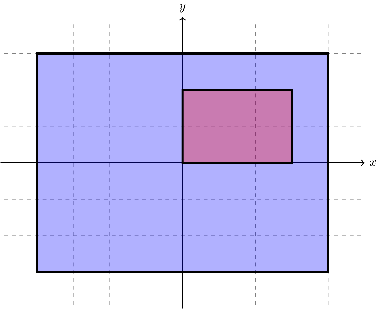
An example case where the operation domain of a node is shown in blue and the domain of an input image is shown in red. Since the input image doesn't completely cover the operation domain of the node, the rest of the blue area for that input image is assumed to be zero.
The previous illustration is a representation of a real world example where one uses the Alpha Over node to overlay a small logo on an image, as shown in the figure below. In that case, the operation domain covers the entirety of the viewport --- as will later be demonstrated, but the logo covers only a small area of it, so the rest of the area is assumed to be a zero transparent color, which is convenient for the use case.
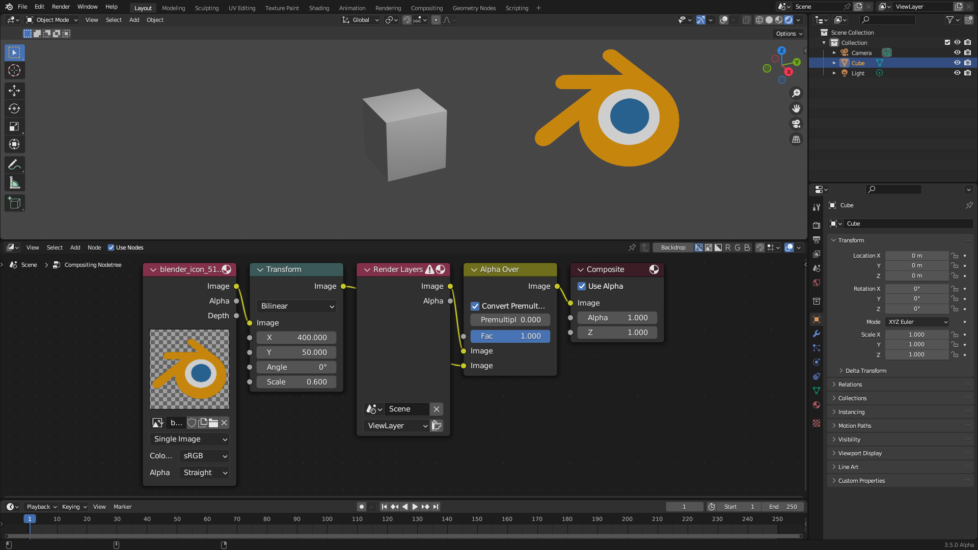
A real world example where the Alpha Over node is used to over a small logo on an image. The logo only covers a small area of the operation domain, which is the whole viewport in this case, so the rest of the area is assumed to be a zero transparent color.
Interpolation
If an input image to a node is not perfectly aligned with the operation domain of the node or have a different size in pixels, the node would typically need to do a process called Interpolation, where the input image is read at the exact positions of the pixels of the operation domain. This can be done using different interpolation methods, including Nearest-Neighbor, Bilinear, and Bicubic interpolations. Those interpolation methods are demonstrated in the following Wikipedia gallery. Transformation nodes like the Transform and Rotate nodes include an interpolation option to set how they prefer their output image to be read and interpolated.
Determining Operation Domain
The question remains on how nodes determine their operation domain. Different node types can have different mechanisms for determining their operation domain. But generally, three classes of nodes exist when it comes to the mechanism of determining the operation domain, each of which is presented in one of the following sections.
Input Nodes
The operation domain of input nodes like the Image node is a domain with an identity transformation and the same size as their outputs, so for the Image node, the operation domain will be the domain whose size is the size of the image and whose transformation is an identity one.
Output Nodes
The operation domain of output nodes like the Viewer node is a domain with an identity transformation and the same size as the final compositor output. For viewport compositing, that size would be the viewport size, and for final render compositing, that size would be the scene render size.
Other Nodes
Unless stated otherwise in their respective documentation pages, all other nodes use the following mechanism. One of the inputs of the nodes is designated as the Domain Input of the node, and the operation domain of the node is identical to the domain of that designated input. For many nodes, the domain input can be intuitively identified as the main input of the node, for instance, the domain input for the Filter node is the Image input. But there are some caveats to note, which requires a deeper understanding of the mechanism.
Each input in the node has the so called Domain Priority property, the operation domain of the node is the domain of the non single value input with the highest domain priority. So for instance, the Filter node has two inputs, the domain priority of the Image input is higher than that of the Factor input, and there are four possible configurations:
Both the Image and factor inputs are connected to images. In this case, the Image input is the domain input because it has the highest priority and is connected to an image.
The Image input is connected to an image, but the Factor input isn't. In this case, the Image input is the domain input because it it is the only input connected to an image regardless of its priority.
The Image input is not connected to an image but the Factor input is. In this case, the Factor input is the domain input because it is the only input connected to an image regardless of its priority.
Neither the Image nor the Factor inputs are connected to images, in this case, there isn't a domain input because the node is evaluated on single values.
Considerations
The aforementioned mechanism for determining the operation domain has a number of consequences that needs to be considered as they might be undesirable, each of which is presented in one of the following sections.
Clipping
The output of nodes will be intuitively clipped to the operation domain, or rather, the domain of the domain input. For instance, if the Foreground input is bigger than the Background input in the Alpha Over node, the output will be clipped to the Background input because it is the domain input, as shown in the following figure.
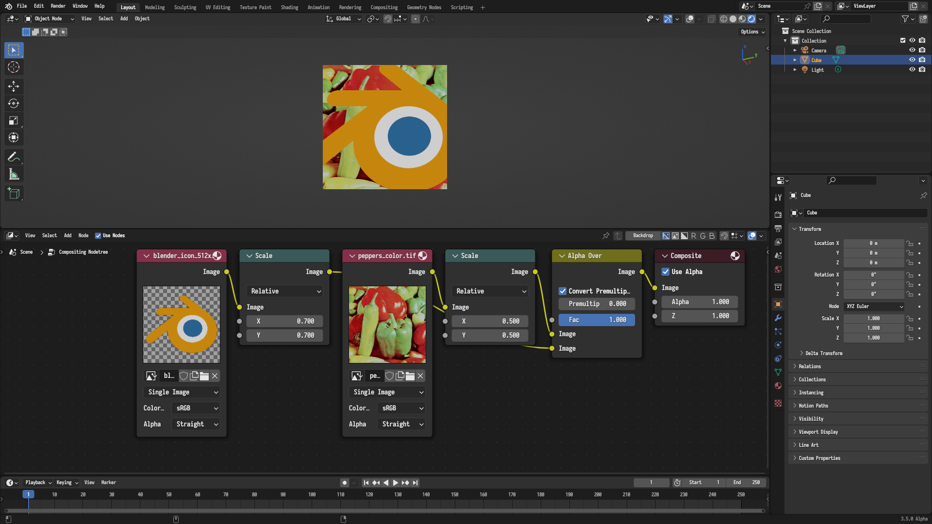
The Foreground input is bigger than the Background input in the Alpha Over node, so the output is intuitively clipped to the Background input because it is the domain input.
The Alpha Over node currently does not support changing the domain priority for its inputs, so as a workaround, one can use a Mix node to achieved the desired behavior, noting that the first Image input in the Mix node has the highest domain priority, as shown in the following figure.
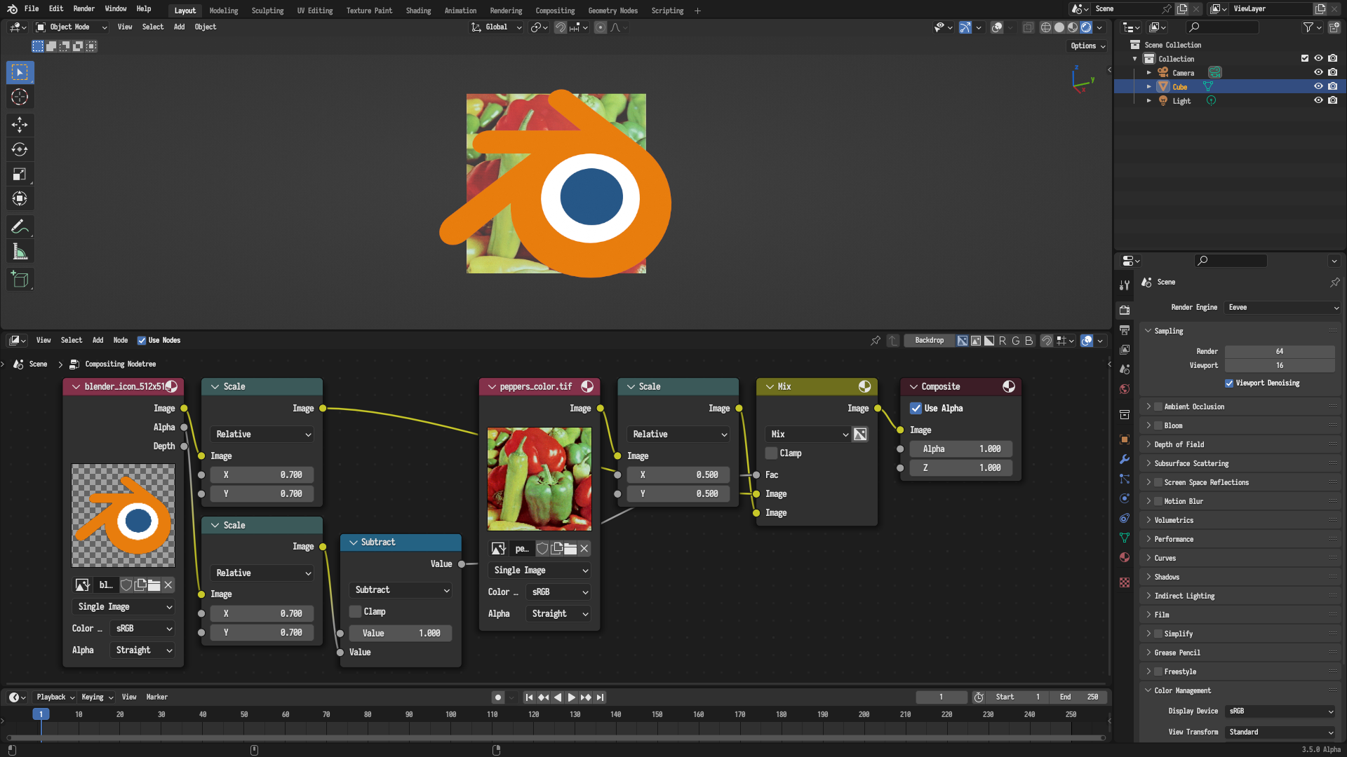
Working around the clipping behavior of the Alpha Over node using a Mix node, noting that the first Image input in the Mix node has the highest domain priority
Output
The GPU compositor only supports a single active output target, that is, only one of the Composite nodes or Viewer nodes in the node tree will be considered active and the rest will be ignored. In particular, the compositor searches the Active Node Tree Context and falls back to the Root Node Tree Context if no active output was found in the active node tree context. The active node tree context is the node tree of an expanded node group, that is, when the users selects a node group node and edits its underlying tree, while the root node tree context is the top level node tree without any expanded node groups. The compositor searches for the active Composite node, if non was found, it searches for the active Viewer node, be it a Viewer or a Split Viewer node, if non was found, the compositor doesn't run altogether. Consequently, note that adding a Viewer node will have no effect if there is a Composite node, since the priority is given to Composite nodes.