Introduction#
There are many ways to select elements, and it depends on what Mesh Select Mode you are in as to what selection tools are available. First we will go through these modes and after that a look is taken at basic selection tools.
Selection Modes#
Reference
- Mode:
Edit Mode
- Menu:
- Shortcut:
1, 2, 3 (Shift Multiple Selection Modes, Ctrl Expand/Contract Selection).
In Edit Mode there are three different selection modes. You can enter the different modes by selecting one of the three buttons in the header.

Edit Mode selection buttons from right to left: Vertex, Edge, Face.#
- Vertex
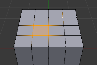
In this mode vertices are shown as points. Selected vertices are displayed in orange, unselected vertices in black, and the active or last selected vertex in white.
- Edge
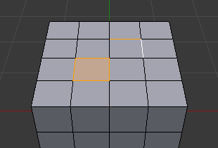
In this mode the vertices are not shown. Instead the selected edges are displayed in orange, unselected edges black, and the active or last selected edge in white.
- Face
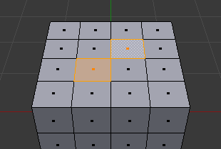
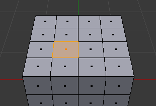
In this mode the faces are displayed with a selection point in the middle which is used for selecting a face. Selected faces and their selection point are displayed in orange, unselected faces are displayed in black, and the active or last selected face is highlighted in white.
When using these buttons, you can make use of modifier keys, see: Switching Select Mode.
Almost all tools are available in all three mesh selection modes. So you can Rotate, Scale, Extrude, etc. in all modes. Of course rotating and scaling a single vertex will not do anything useful (without setting the pivot point to another location), so some tools are more or less applicable in some modes.
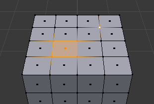
See Fig. Selection modes. for examples of the different modes.
Multiple Selection Modes#
By holding Shift-LMB when selecting a selection mode, you can enable multiple Selection Modes at once. This allows you to quickly select vertices, edges, or faces, without first having to switch mode.
Switching Select Mode#
When switching modes in an “ascendant” way (i.e. from simpler to more complex), from Vertices to Edges and from Edges to Faces, the selected parts will still be selected if they form a complete element in the new mode.
For example, if all four edges in a face are selected, switching from Edges mode to Faces mode will keep the face selected. All selected parts that do not form a complete set in the new mode will be unselected.
Hence, switching in a “descendant” way (i.e. from more complex to simpler), all elements defining the “high-level” element (like a face) will be selected (the four vertices or edges of a quadrangle, for example).
Expand/Contract Selection#
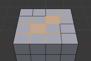
By holding Ctrl when selecting a higher selection mode, all elements touching the current selection will be added, even if the selection does not form a complete higher element. Or contracting the selection when switching to a lower mode.
X-Ray#
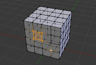
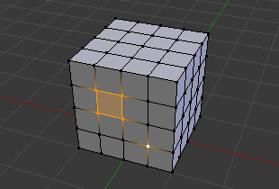
The X-Ray setting is not just for shading, it impacts selection too. When enabled, selection isn’t occluded by the objects geometry (as if the object was solid).
Known Issues#
Dense Meshes#
Selecting dense meshes with X-Ray disabled, has a limitation where dense meshes may not have all the elements selected. When selecting regions with Box, Circle and Lasso select, vertices may overlap each other causing some vertices not to be selected. This is a limitation with the current selection method, you may workaround this by zooming in or enabling X-Ray.
N-Gons in Face Select Mode#
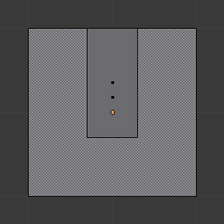
N-gon face having its center dot inside another face.#
As already noted, in X-Ray and Wireframe mode faces are marked with a dot in the middle. With n-gons that can lead in certain cases to a confusing display. The example shows the center dot of the U-shaped n-gon being inside of the oblong face inside the “U”. It is not easy to identify which dot belongs to which face (the orange dot in the image is the object origin).
